

Image processing method and image processing device
a technology of image processing and image processing algorithm, applied in the field of image processing method and image processing device, can solve problems such as the performance decline of image processing algorithm, and achieve the effect of reducing the regular reflection light componen
- Summary
- Abstract
- Description
- Claims
- Application Information
AI Technical Summary
Benefits of technology
Problems solved by technology
Method used
Image

Examples
embodiment 1
[0047]The following description will discuss details of Embodiment 1 of the present invention. An image processing device in accordance with Embodiment 1 is a device which carries out authentication based on a picture image of an iris of an eyeball of a human.
[0048](Overview of Image Processing Device 10)
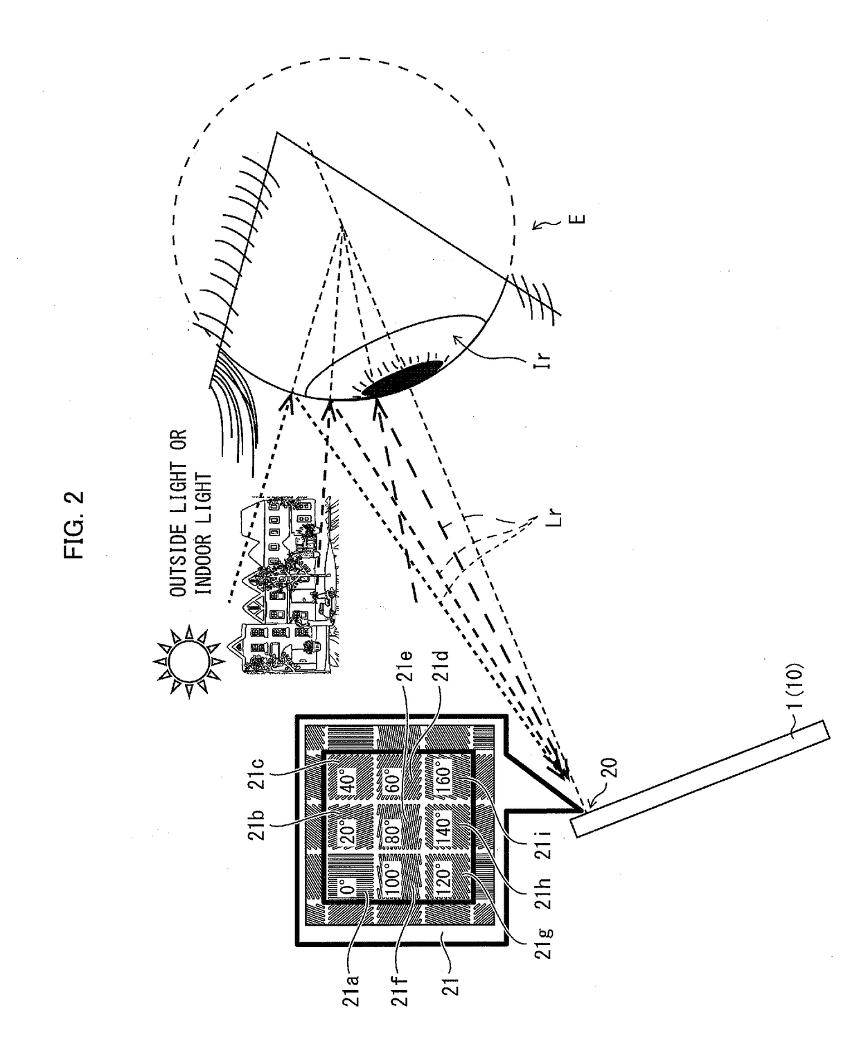
[0049]First, the following description will discuss an overview of an image processing device 10. FIG. 2 is a view for explaining an overview of the image processing device 10. The image processing device 10 carries out image processing with respect to a picture image of a subject. Specifically, the image processing device 10 carries out a process of separating a diffuse reflection component from a specular reflection component which are contained in reflected light from the subject. In Embodiment 1, the image processing device 10 is mounted on a personal digital assistant 1.
[0050]The personal digital assistant 1 is, for example, a terminal which can separate the above two reflectio...
experimental example 1
[0125]The following description will discuss, with reference to an experimental example using a rubber ball, a reason why an image (reflected image) which is a noise included in a picture image can be removed by the image processing device 10 through the above described second process carried out by the S-polarized light calculating section 12. The camera 20 used in the experiment is a camera having a CCD sensor and the number of pixels is 1900×900 (i.e., approximately 1.3 million pixels). The integrated polarizer included in the camera 20 has four polarizing elements whose polarization angles are different from each other. In the descriptions below, the polarization angles of the four polarizing elements are 0°, 45°, 90°, and 135°, respectively.
[0126]The polarizing element is manufactured as follows. First, a film of AlCu having a film thickness of 40 nm is formed, via an SiO2 interlayer film, on a photodiode which constitutes the CCD sensor, and slits (i.e., belt-like regions in w...
experimental example 2
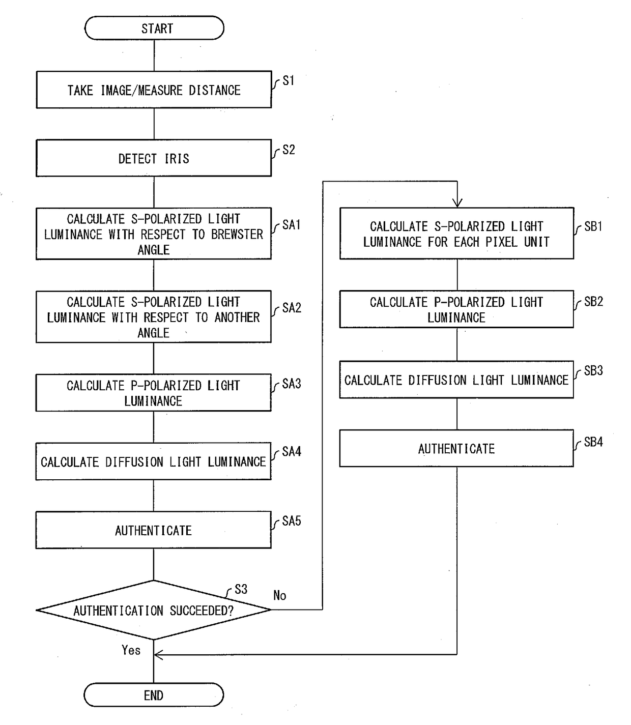
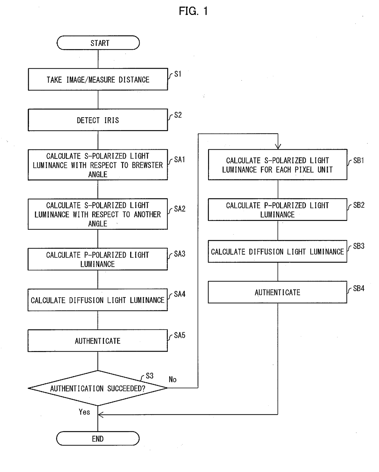
[0136]FIG. 12 is a view showing an overview of a picture image showing experimental results of image processing carried out by the image processing device in accordance with Embodiment 1. In Experimental Example 2, an integrated polarizer including seven polarizing elements whose polarization angles are different from each other is used. Moreover, in Experimental Example 2, image processing is carried out by the steps SB1 through SB3 in the above described flowchart.
[0137]Before image processing, a picture image used in Experimental Example 2 includes a reflected image Ir of outside light in the iris region, as illustrated in a part from which the arrow extends in FIG. 12. On the other hand, after the image processing, the reflected image Ir of outside light in the iris region has been removed, as illustrated in a part which is pointed out by the arrow in FIG. 12.
[0138](Effect of Image Processing Device 10)
[0139]The inventor carried out experiment of authentication by a conventional...
PUM
 Abstract
Description
Claims
Application Information