
A rotary milking parlour arrangement

a parlour and rotating technology, applied in the field of rotary milking parlour arrangement, can solve the problems of difficult for dirt and washing water to penetrate the space under the platform and reach, and the surface around and on the rotary platform is quickly dirty, so as to increase the safety of operators

Active Publication Date: 2017-11-09
DELAVAL HLDG AB
View PDF4 Cites 1 Cited by
  • Summary
  • Abstract
  • Description
  • Claims
  • Application Information

AI Technical Summary

Benefits of technology

The present invention is a modular unit for a rotary milking parlour that increases safety for operators and protects sensitive components from damage. It achieves this by creating a closed space for the milking components, away from the platform and its dirty surfaces. The modular unit rotates with the platform and includes a front wall element to prevent dirt and water from reaching the milking components. This results in a cleaner and safer environment for the operators. Additionally, the front wall element provides protection between components and operators, and it is easy to clean and manufacture. The invention consists of a metal sheet, which provides high strength and corrosion resistance, and an aperture to access the milking components. The closed space can be formed as a cabinet or without a closed space, depending on the needs. Overall, the invention enhances safety and efficiency in the milking process.

Problems solved by technology

The surfaces around and on a rotary platform quickly become dirty and cleaning water is regularly spoiled on said surfaces.
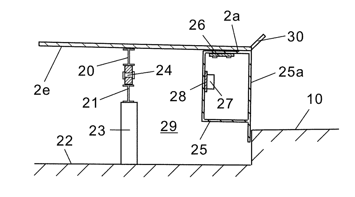
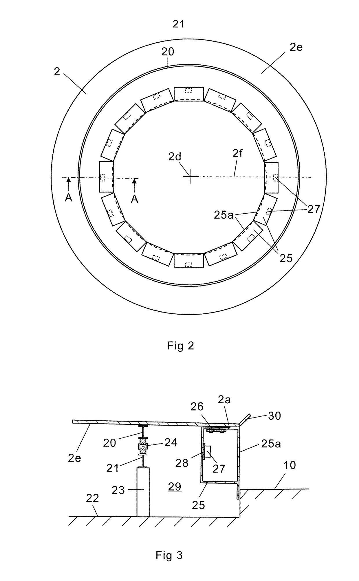
Such a front wall element will at least make it difficult for dirt and washing water to penetrate into the space under the platform and reach the milking component in its mounting position under the platform.
Thereby, dirt and washing water will not come in contact with and reduce the life time of the milking component.

Method used


Image

  • A rotary milking parlour arrangement
  • A rotary milking parlour arrangement
  • A rotary milking parlour arrangement

Examples


Embodiment Construction

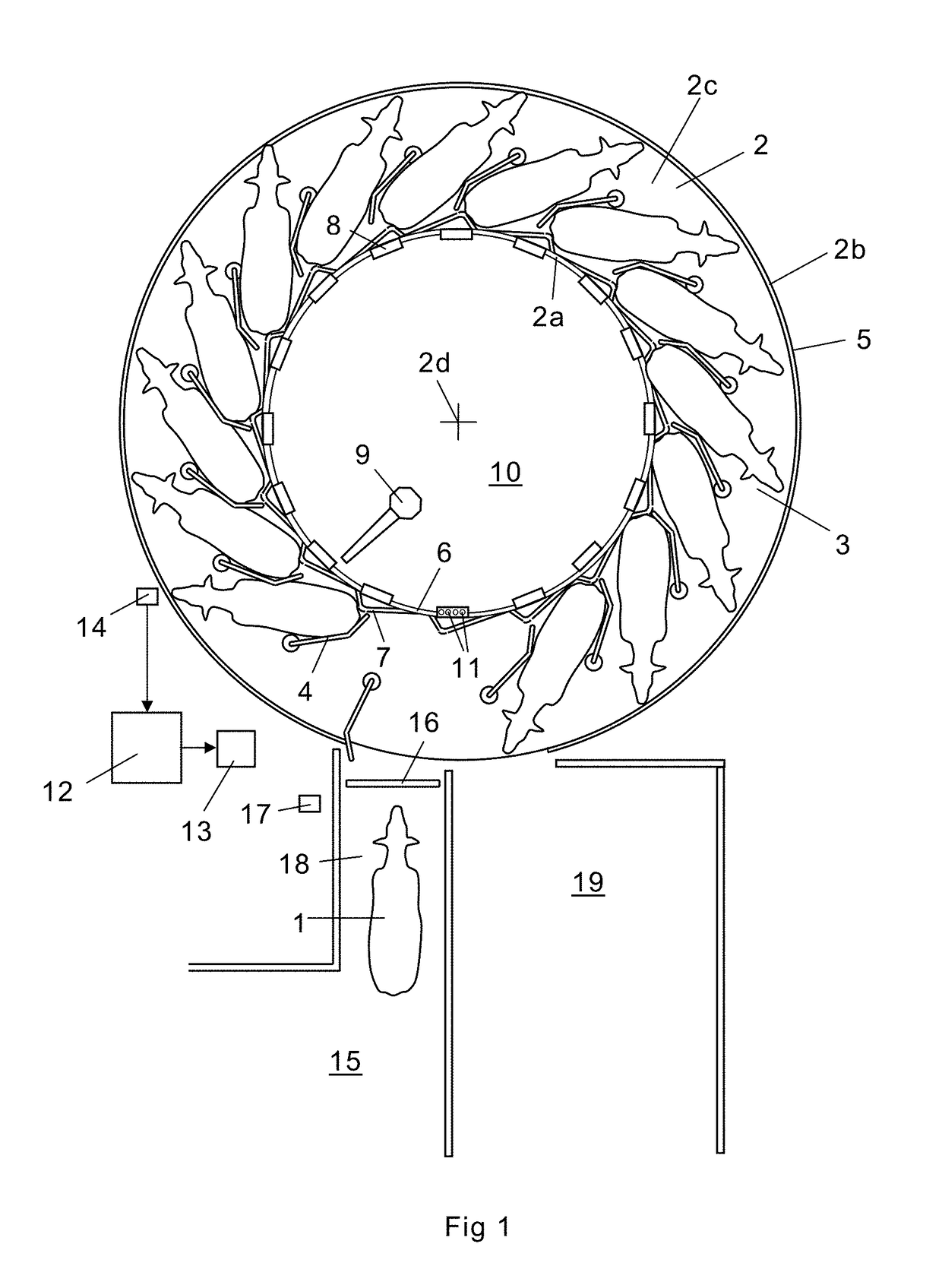
[0029]FIG. 1 shows a rotary milking parlour for milking of cows 1. The milking parlour comprises an annular platform 2 having an inner edge portion 2a and an outer edge portion 2b. The platform 2 rotates during operation around a vertical rotary axis 2d. The platform 2 has an upper surface 2c forming a support surface for the cows 1 to be milked on the platform 2. A plurality of rotatable fence members 4 are arranged on the upper surface 2c of the platform 2. The rotatable fence members 4 are used for dividing the platform 2 into milking stalls 3 for receiving individual cows 1 in predetermined milking positions. By the use of rotatable fence members 4, it is possible to position the cows very close together on the platform 2. An outer fence arrangement 5 is mounted around a common part of the outer periphery of the platform 2. An inner fence arrangement 6 and a rumprail 7 are arranged at the inner edge portion 2a of the platform 2. The object of the rumprail 7 is to position the re...


PUM


Abstract

A rotary milking parlor arrangement comprising an annular platform rotatably arranged around a rotary axis, a plurality of milking stalls arranged on the platform, a stationary floor surface surrounded by an inner edge portion of the annular platform. The floor surface is provided at a lower elevation than the platform surrounding it, such that a vertical opening is formed to a space under the platform between the edge portion of the platform and the floor surface. Modular units, located in the space under the platform, comprise a front wall element closing a part of said vertical opening, the modular units configured to be attached to a lower surface of the platform and to house at least one milking component in the space under the platform.

Description

THE BACKGROUND OF THE INVENTION AND PRIOR ART[0001]The present invention relates to a rotary milking parlour arrangement comprising an annular platform rotatably arranged around a rotary axis, a plurality of milking stalls arranged on the platform, a stationary floor surface arranged at the side of an edge portion of the platform, wherein the floor surface is located at a lower level than the platform such that a vertical opening is formed to a space under the platform between the edge portion of the platform and the floor surface, and a modular unit configured to be attached to the platform in a mounting position configured to house at least one milking component.[0002]In a conventional rotary milking parlour, the cows walk on to an annular rotating platform and enter a milking stall. Teat cups are attached to the cows by means of an operator or a robot arm standing on a floor surface at the side of the platform. The platform usually rotates with a constant low speed in relation to...

Claims


Application Information

Patent Timeline
Patent Type & Authority Applications(United States)
IPC IPC(8): A01K1/12A01J5/007
CPCA01K1/126A01J5/007A01K1/12
Inventor KRONEKVIST, HANSBRATT, MILANLANDAU, DAVIDAYE, KLAUS
Owner DELAVAL HLDG AB
Learn More