Eureka AIR delivers breakthrough ideas for toughest innovation challenges, trusted by R&D personnel around the world.

Device for use in hysteroscopy

a technology for hysteroscopy and devices, applied in the field of hysteroscopy devices, can solve the problems of large amount of permanently or semi-permanently installed devices, complex equipment, and difficulty in purchasing and maintaining equipment, and achieve the effect of requiring skills and training for sta

Inactive Publication Date: 2017-11-09
LINA MEDICAL
View PDF12 Cites 174 Cited by
  • Summary
  • Abstract
  • Description
  • Claims
  • Application Information

AI Technical Summary

Benefits of technology

The invention aims to improve the quality of devices used for hysteroscopy (a medical procedure that allows for the inspection of the uterus) by reducing the risk of contamination and ensuring safety during use. The goal is also to make the devices easier to insert and use with other tools, such as forceps or scissors. Overall, the patent aims to make the hysteroscopy process more effective and reliable.

Problems solved by technology

In the medical field, the large amount of permanently or semi-permanently installed devices is challenging.
The costs for purchasing and costs for maintenance of the equipment, and the complexity necessitate skills and training for the staff.
Additionally, the technical equipment takes up space, they require fixed power supply, and / or supply of fluids etc., and they may be impossible to move close to the practitioner during surgery and therefore they may sometimes be in the way for the staff and they can be difficult to use.
Sterility can be accomplished by using a device only once, but typically, the large electrical fixtures including endoscopes and monitors of an operating room are much too expensive to be used only once.
The existing endoscopes are typically two-unit devices made of a relatively inexpensive scope with a camera or with fiber optics, and a very expensive control unit forming part of the fixture of an operating room.
The existing endoscopes are complicated to use and require adaption of settings between the scope and the control unit.
Additionally, sterility can be compromised when the non-sterile control unit is connected to the sterile scope by cables.
Such devices are simple to use but typically provide a limited set of operating features as compared with the known two unit devices.

Method used


Image

  • Device for use in hysteroscopy
  • Device for use in hysteroscopy
  • Device for use in hysteroscopy

Examples


embodiment 1

[0109]2. A device , where the image capturing structure is movable relative to the distal end of the elongated member.

embodiment 2

[0110]3. A device , where the image capturing structure is connected to the distal end by elastically deformable means.

[0111]4. A device according to any of the preceding embodiments, where the elongated member forms an elongated conduit between a proximal opening and a distal opening.

embodiment 4

[0112]5. A device , comprising a valve structure configured to seal between an inner surface of the elongated conduit and an outer surface of an instrument arranged in the elongated conduit.

[0113]6. A device according to any of embodiments 2-3 and any of embodiments 4-5, where the image capturing structure is movable between a first position in which it at least partly hinders passage through the elongated conduit and a second position providing unhindered passage through the elongated conduit.

[0114]7. A device according to any of the preceding embodiments, where the image capturing structure comprises a camera and an electronic circuit for converting the image into an electrical signal.


PUM


Abstract

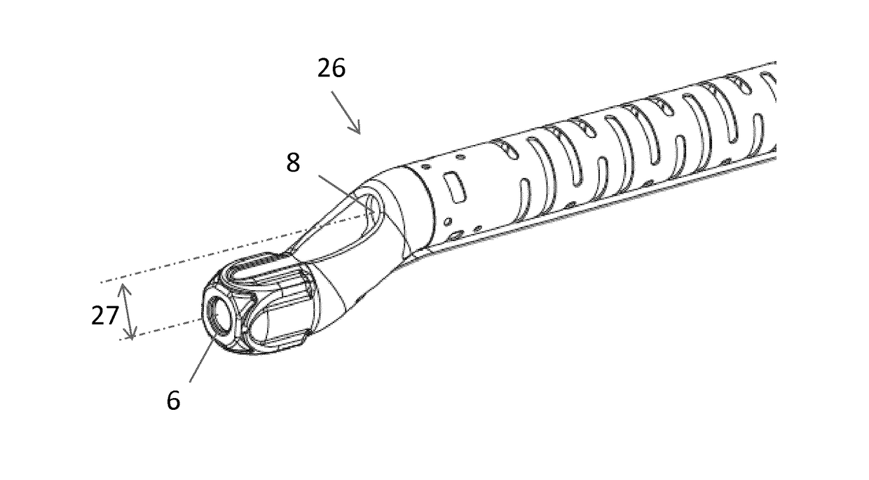
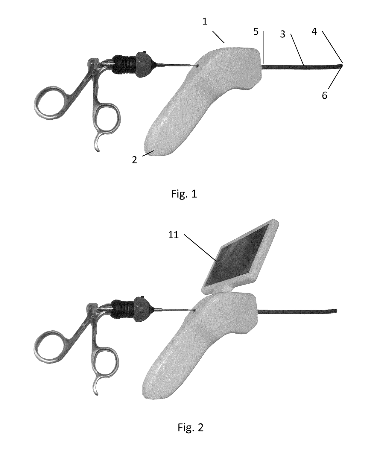
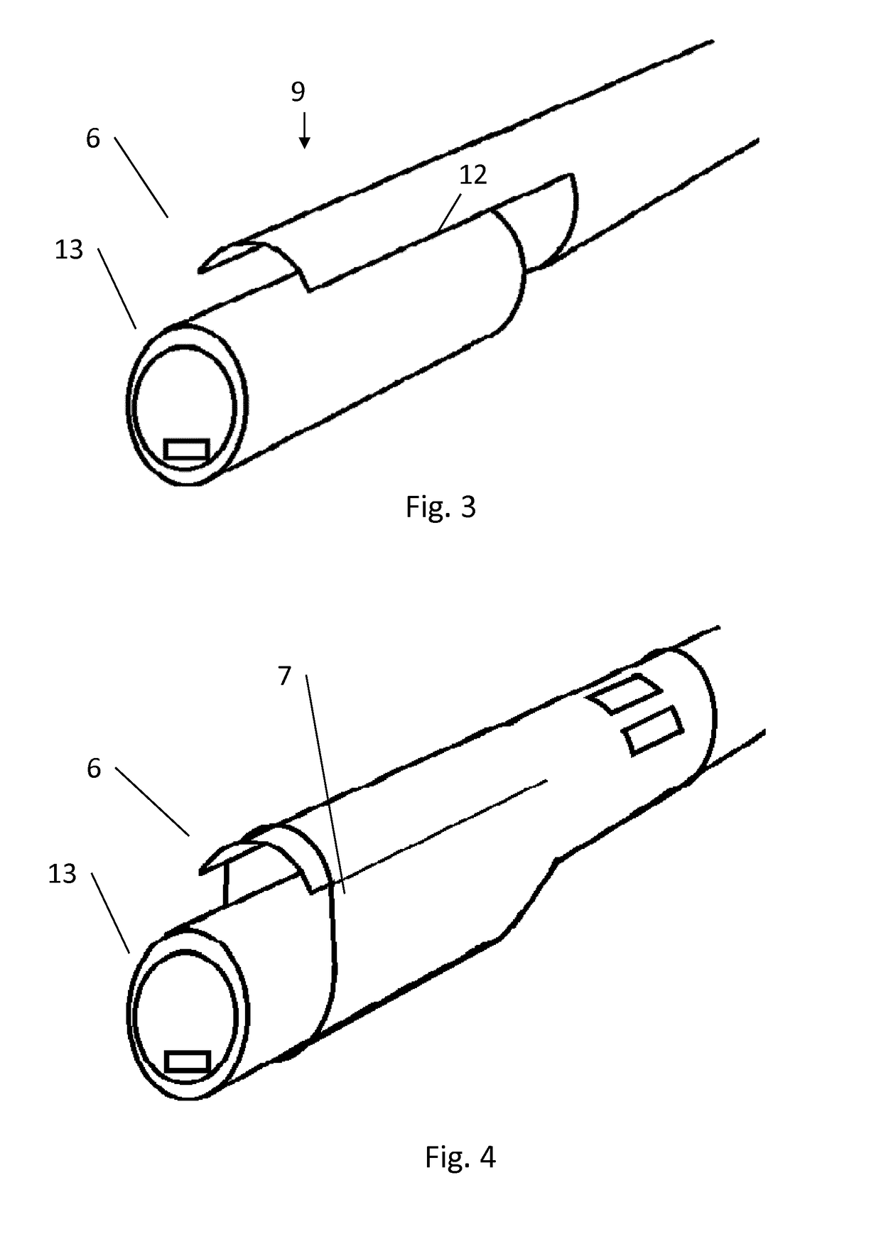
A hysteroscopy device with an image capturing structure located at a distal end of an elongated member and communicating video signals with a monitor. The elongated member and the image capturing structure being dimensioned for insertion into the patient's uterus through cervix.

Description

INTRODUCTION[0001]The present invention relates to a portable device for use in hysteroscopy.BACKGROUND[0002]Gynecologists use hysteroscopy in standard examination procedures, both in office-based procedures and in hospital procedures. In hysteroscopy, an endoscope is inserted into the uterus e.g. for inspecting the lining.[0003]For the practitioner, the field of diagnostic imaging, for example hysteroscopy, has allowed viewing of the internal lining in uterus with minimal complication and pain.[0004]Such imaging tools have been used in different forms for detailed different kinds of inspection.[0005]In the medical field, the large amount of permanently or semi-permanently installed devices is challenging. The costs for purchasing and costs for maintenance of the equipment, and the complexity necessitate skills and training for the staff.[0006]Additionally, the technical equipment takes up space, they require fixed power supply, and / or supply of fluids etc., and they may be impossib...

Claims


Application Information

Patent Timeline
IPC IPC(8): A61B1/00A61B1/005A61B1/05A61B1/303
CPCA61B1/0008A61B1/303A61B1/05A61B1/005
Inventor POULSEN, HENRIK BISGAARDRASMUSSEN, ANDERSANDERSEN, JONAS
Owner LINA MEDICAL
Why Eureka
Eureka Blog
Learn More