Light shielding structure of electronic device

a technology of electronic devices and shielding structures, applied in the field of light shielding structures, can solve the problems of inability to simply alter or control the brightness/darkness of lighting, the light so projected out may inadvertently shine on the eyes of people staying nearby, and the eye attraction is too high to be used in private use, etc., to achieve convenient use, avoid unpleasantness, and maintain sharpness and recognizability

Inactive Publication Date: 2017-11-09
EVGA CORPORATION
View PDF2 Cites 0 Cited by
  • Summary
  • Abstract
  • Description
  • Claims
  • Application Information

AI Technical Summary

Benefits of technology

[0004]The primary object of the present invention is to avoid unpleasantness caused by undesired shining of light on the eyes of other people.
[0005]Another object of the present invention is to prevent other people from getting aware of an electronic being in operation.
[0006]A further object of the present invention is to enable variation of brightness as desired while maintain sharpness and recognizability.
[0007]To achieve the above objects, the present invention comprises at least one display device and an outer casing that are mounted to an electronic device. The outer casing is arranged at one side of the display device. The outer casing comprises at least one light transmitting portion mounted therein for light from the display device to transmit therethrough. At least one adjustable light-shielding plate that is operable to change color is arranged between the light transmitting portion and the display device. At least one adjusting device is set on at least one side of the adjustable light-shielding plate and operatively coupled thereto. The adjusting device is provided for operation by a user to selectively change the color of the adjustable light-shielding plate. In the use of the electronic device, the display device emits light and the user may operate the adjusting device to cause the adjustable light-shielding plate to change color for shielding light so as to prevent light from transmitting through the adjustable light-shielding plate and the light transmitting portion. Further, the user may makes the adjustable light-shielding plate in an idle condition and thus not in operation so that light from the display device is allowed to transmit through the adjustable light-shielding plate and the light transmitting portion, whereby the light may be projected from the outer casing. With such a technical solution, the drawbacks of the prior art that the backlighting display structure does not allow for control of brightness / darkness of illumination so as to cause unpleasantness of other people and does not allow for use in private can be effectively overcome and effects of being easy to use, being aesthetics and eye attracting, use in private, and being free of interference with other people can be achieved.

Problems solved by technology

However, since light that is projected through the characters or figures (formed of the light-transmitting board) comes from the backlight module, it is not possible to simply alter or control brightness / darkness of the lighting.
Thus, it may sometimes get too eye attracting to be used in private.
In addition, the light so projected out may inadvertently shine on the eyes of people staying nearby.
This may cause unpleasant situations.

Method used


Image

  • Light shielding structure of electronic device
  • Light shielding structure of electronic device
  • Light shielding structure of electronic device

Examples


Embodiment Construction

[0021]The following descriptions are exemplary embodiments only, and are not intended to limit the scope, applicability or configuration of the invention in any way. Rather, the following description provides a convenient illustration for implementing exemplary embodiments of the invention. Various changes to the described embodiments may be made in the function and arrangement of the elements described without departing from the scope of the invention as set forth in the appended claims.

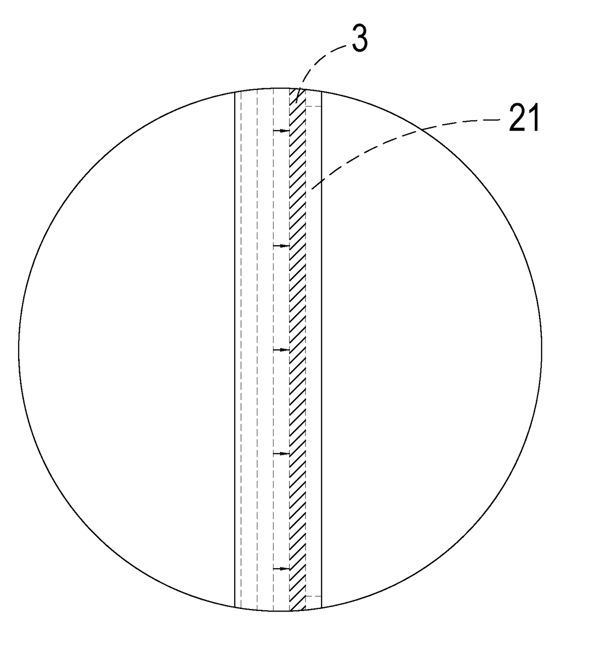
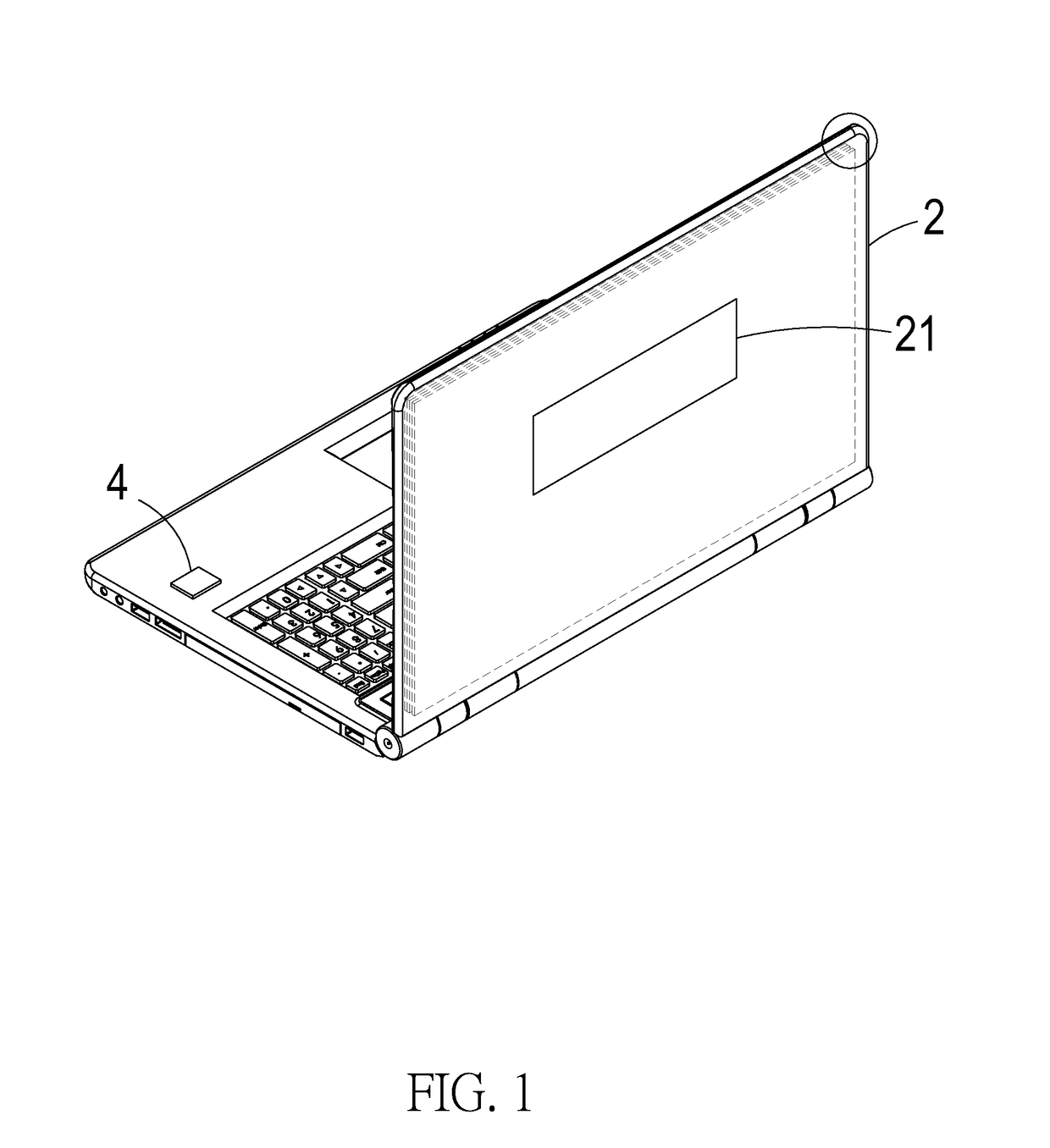
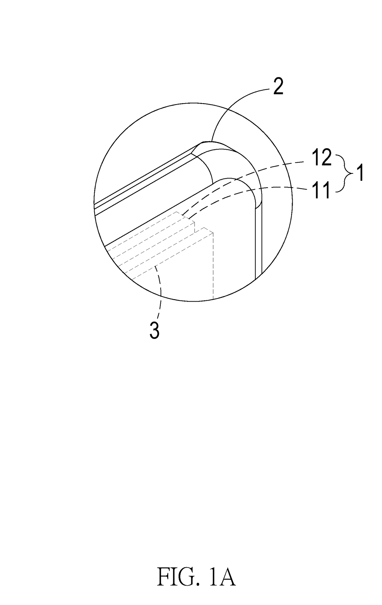
[0022]Referring to the illustrations of FIGS. 1 and 2, it is clearly seen that the present invention comprises at least one display device 1 mounted to an electronic device, at least one outer casing 2 mounted to the electronic device, at least one light transmitting portion 21, at least one adjustable light-shielding plate 3, and at least one adjusting device 4, wherein the outer casing 2 is arranged at one side of the display device 1 and the light transmitting portion 21 is mounted on the outer c...


PUM


Abstract

A light shielding structure is provided for an electronic device and includes a display device mounted to the electronic device, an outer casing arranged at one side of the display device, a light transmitting portion mounted on the outer casing, an adjustable light-shielding plate arranged between the display device and the light transmitting portion, and an adjusting device set on one side of the adjustable light-shielding plate and operatively coupled thereto. When the display device is activated, light transmits toward the adjustable light-shielding plate. When the adjustable light-shielding plate is in an idle and not operating condition, the light is allowed to transmit through the adjustable light-shielding plate and the light transmitting portion to make light projecting out from the outer casing. Oppositely, the adjusting device may be operated to cause the adjustable light-shielding plate to change color for shielding the light.

Description

(a) TECHNICAL FIELD OF THE INVENTION[0001]The present invention relates generally to a light shielding structure, and more particularly to a light shielding structure that allows for use in private and prevents interference with the electronic devices of other people.(b) DESCRIPTION OF THE PRIOR ART[0002]A conventional backlighting display structure generally comprises a backlight module that provides lighting to a screen, a back cover that is arranged backwards of the screen, and a light-transmitting board mounted in and extending through the back cover. The light-transmitting board is generally formed with a pattern of characters or figures so that when the screen is set on, light emitting from the backlight module transmits through the light-transmitting board, this helping save energy and allowing observers to directly view the characters or figures (formed of the light-transmitting board) through which light is projected out so as to improve aesthetics and eye attraction.[0003]...

Claims


Application Information

Patent Timeline
Patent Type & Authority Applications(United States)
IPC IPC(8): G02B5/22
CPCG02B5/22G02F1/133308G02F1/133606G02F1/133314
Inventor HAN, TAI-SHENG
Owner EVGA CORPORATION
Why Eureka
Try Eureka