Ventilation system
A technology of ventilation system and state, applied in the field of ventilation system
- Summary
- Abstract
- Description
- Claims
- Application Information
AI Technical Summary
Problems solved by technology
Method used
Image
Examples
Embodiment approach 1
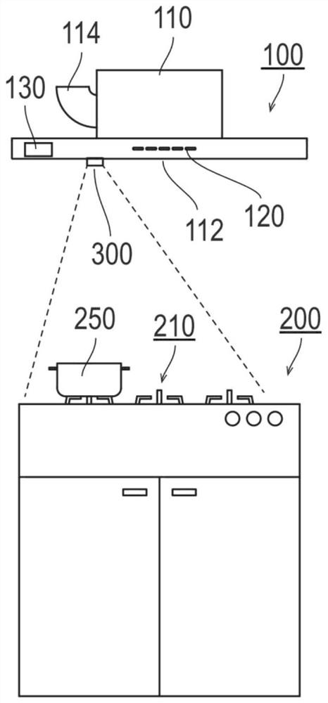
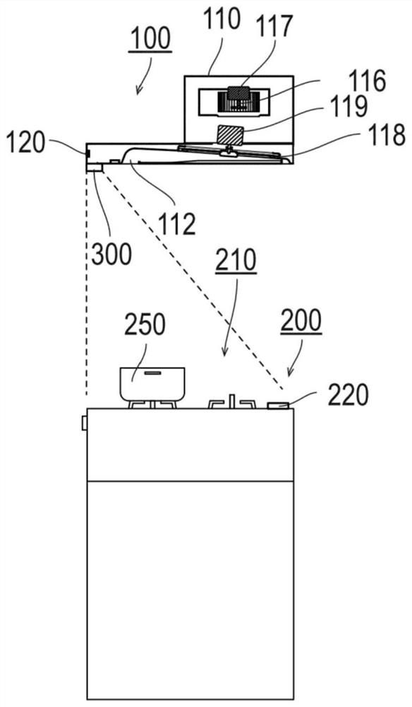
[0050] Figure 7 It is an operation flowchart showing the control of the operating state of the range hood in Embodiment 1. This operation flowchart is also processed by the control unit 130 . Among them, on the operation panel 120 (refer to image 3 as well as Figure 5 ) when the air volume automatic switch 123 is pressed and the range hood 100 runs automatically, this action flow chart is executed. Therefore, the control unit 130 controls the air volume of the fan 116 and / or the rotation speed of the filter 118 based on the temperature detected by the compound eye temperature sensor 300 , and independently controls the subsequent automatic operation.
[0051] First, the control part 130 detects the temperature of the upper part of the cooker 200 by the compound eye temperature sensor 300 (S200). like Figure 4 As shown, the compound eye temperature sensor 300 can be divided into 64 areas to detect the temperature above the cooker 200 . For example, when cooking is per...
Embodiment approach 2
[0056] Figure 8 It is an operation flowchart showing the control of the operating state of the range hood according to the second embodiment. This operation flowchart is also processed by the control unit 130 . Wherein, this operation flowchart is also executed when the range hood 100 is automatically operated.
[0057] First, the control part 130 detects the temperature of the upper part of the cooker 200 by the compound eye temperature sensor 300 (S300).
[0058] Next, the control unit 130 judges whether or not the temperature difference of each pixel in the temperature rise range detected by the compound eye temperature sensor 300 has changed to a state within a specific predetermined range ( S310 ). When the temperature of the cooking utensil 250 is different from that of the cooking item, or when the cooking item is scattered in the cooking utensil 250 (stir-frying, etc.), the temperature distribution appears scattered during cooking. However, when the cooking tool 25...
Embodiment approach 3
[0062] Figure 9 It is an operation flowchart showing the control of the operating state of the range hood according to the third embodiment. This operation flowchart is also processed by the control unit 130 . Wherein, this operation flowchart is also executed when the range hood 100 is automatically operated.
[0063] First, the control part 130 detects the temperature of the upper part of the cooker 200 by the compound eye temperature sensor 300 (S400).
[0064] Next, the control unit 130 judges whether or not the temperature rise range detected by the compound eye temperature sensor 300 has moved by a predetermined value or more than a predetermined time ago ( S410 ). For example, when the cooker 250 is used to cook a cooking item, if the cooker 250 is moved, the temperature rise ranges of the cooker 250 and the cooker gradually deviate in the moving direction. In addition, when the cooking utensil 250 is moved from the heat source 210A, the portion where the heat source ...
PUM
 Abstract
Description
Claims
Application Information
 - R&D
- Intellectual Property
- Life Sciences
- Materials
- Tech Scout
- Unparalleled Data Quality
- Higher Quality Content
- 60% Fewer Hallucinations
Browse by: Latest US Patents, China's latest patents, Technical Efficacy Thesaurus, Application Domain, Technology Topic, Popular Technical Reports.
© 2025 PatSnap. All rights reserved.Legal|Privacy policy|Modern Slavery Act Transparency Statement|Sitemap|About US| Contact US: help@patsnap.com


