
Image process based, dynamically adjusting vehicle surveillance system for intersection traffic

a vehicle surveillance and traffic technology, applied in the field of surveillance devices and methods, can solve the problems of reducing the overall cost, affecting the accuracy of the surveillance system, so as to improve the accuracy, reduce the cost of surveillance devices, and reduce the installation cost.

Inactive Publication Date: 2017-11-16
KARABED RAZMIK
View PDF11 Cites 4 Cited by
  • Summary
  • Abstract
  • Description
  • Claims
  • Application Information

AI Technical Summary

Benefits of technology

The patent describes a new design for a surveillance system that reduces cost and improves durability and viewing quality. The new design eliminates the need for a device that rotates the camera, which is the main cost area of the conventional design. This reduction in cost also means that the end switch used in calibration is also unnecessary. Additionally, by eliminating the rotating camera, the system is less susceptible to wear and tear and produces improved viewing quality. The new design also simplifies the installation process by eliminating the need for wires that reach inside the side-mirror housing and doors of the vehicle.

Problems solved by technology

The motor that rotates the camera is a major cost and a potential area for maintenance.
The device that rotates the camera in the conventional design is one of the major cost areas of the dynamically adjustable surveillance system; therefore, the elimination of the device that rotates the camera lowers the overall cost.
This elimination makes the end switch used in the calibration of the conventional device useless, therefore further reducing cost.
Since the device that rotates the camera is the major moving part of the conventional surveillance device, it is the most susceptible to wear and tear.

Method used


Image

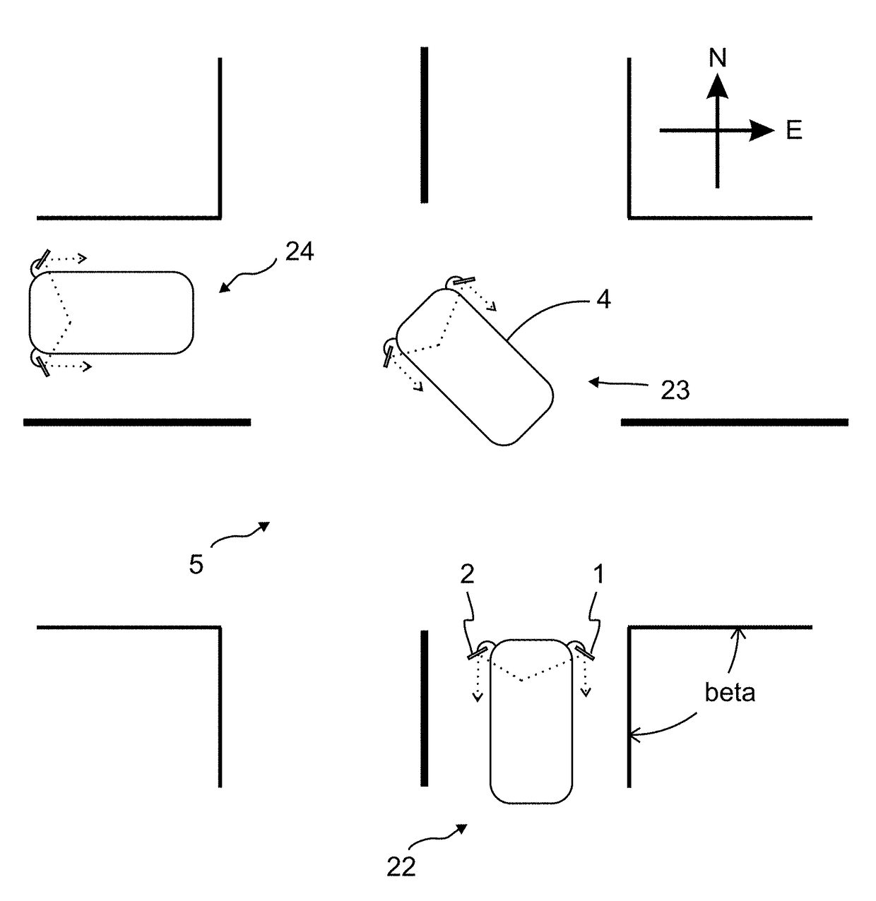
  • Image process based, dynamically adjusting vehicle surveillance system for intersection traffic
  • Image process based, dynamically adjusting vehicle surveillance system for intersection traffic
  • Image process based, dynamically adjusting vehicle surveillance system for intersection traffic

Examples


example 1

[0072]Example 1 is explained referring to FIGS. 3 through 6.

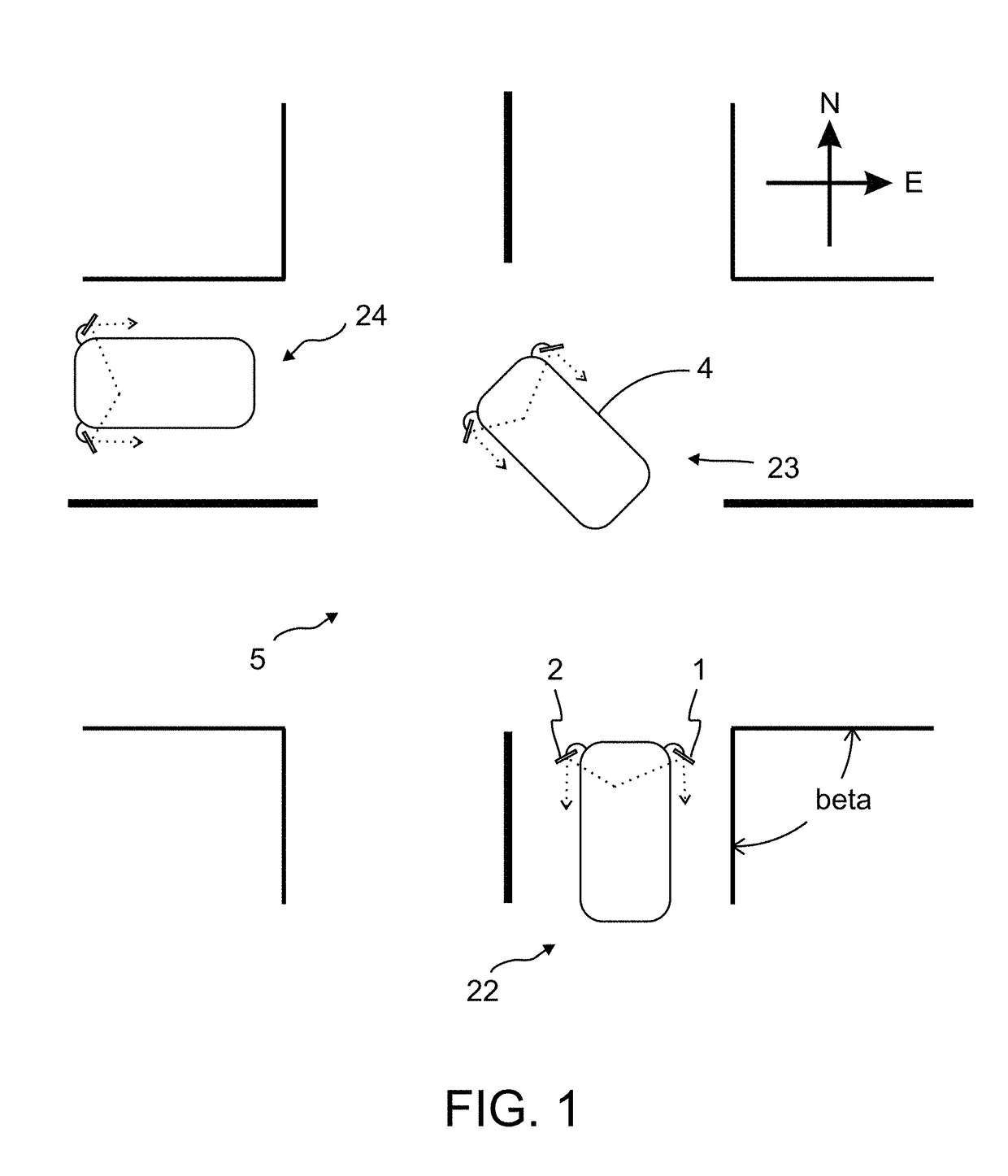
[0073]This example relates to scenario A4—referring to a view in the left-side mirror during a right turn. More specifically, an image process based, dynamically adjusting vehicle surveillance system for intersection traffic of Example 1 alleviates the shortcomings of the left-side mirror during right turns as explained earlier.

[0074]Here, the key desired view is a view of a left-side mirror when the vehicle is not turning right at an intersection, and the desired view is a view of a road section opposite to that of the road section into which the vehicle is turning; that is, a view of the cross traffic from the left side when the vehicle is turning right at an intersection.

[0075]FIG. 3 gives a block diagram of the image process based, dynamically adjusting vehicle surveillance system for intersection traffic. The image process based, dynamically adjusting vehicle surveillance system for intersection traffic includes a came...

example 2

[0153]Example 2 is explained using FIGS. 3, 6 and 9.

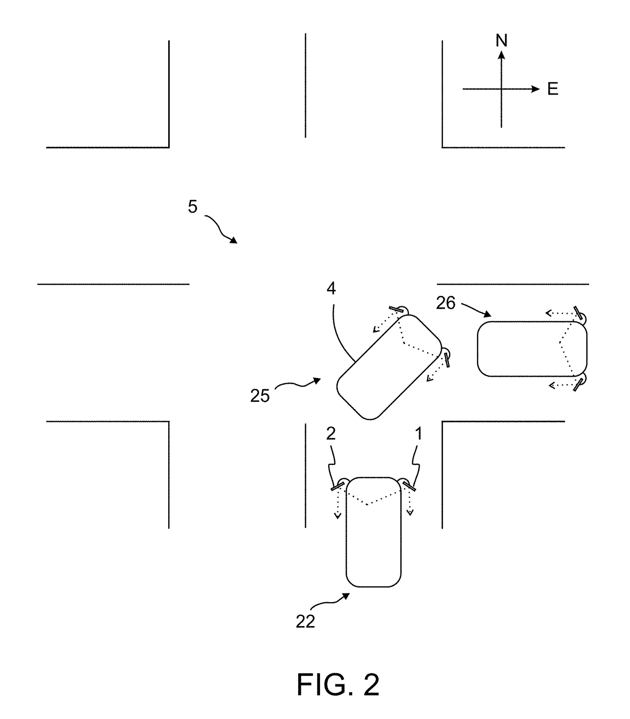
[0154]This example relates to scenario A1—referring to a view in the right-side mirror during left turn. More specifically, an image process based, dynamically adjusting vehicle surveillance system for intersection traffic of Example 2 alleviates the shortcomings of the right-side mirror during left turns as explained earlier.

[0155]Here the key desired view is a view of a right-side mirror when the vehicle is not turning left at an intersection, and the desired view is a view of a road section opposite to that of the road section into which the vehicle is turning; that is, a view of the cross traffic from the right side when the vehicle is turning left at an intersection.

[0156]FIG. 3 gives a block diagram of the image process based, dynamically adjusting vehicle surveillance system for intersection traffic of Example 2. The image process based, dynamically adjusting vehicle surveillance system for intersection traffic of Example 2 ...

example 3

[0180]Example 3 is explained using FIGS. 7, 10, and 8.

[0181]This example relates to scenario A3—referring to a view in the left-side mirror during left turn. More specifically, an image process based, dynamically adjusting vehicle surveillance system for intersection traffic of Example 3 alleviates the shortcomings of the left-side mirror during left turns as explained earlier.

[0182]Here the key desired view is a view of a left-side mirror when the vehicle is not turning left at an intersection, and the desired view is a view of a road section toward behind the vehicle on the left side before a turn is initiated when the vehicle is turning left at an intersection.

[0183]FIG. 7 gives a block diagram of the image process based, dynamically adjusting vehicle surveillance system for intersection traffic of Example 3. The image process based, dynamically adjusting vehicle surveillance system for intersection traffic of Example 3 includes the camera 10, the controller and memory unit 20, t...


PUM


Abstract

A dynamically adjusting surveillance system provides a monitor, a sequence of views that include a key view. The sequence of views is captured by a camera. The monitor can display a portion of the camera view. The system is configured such that the displayed portion of the camera view includes the key view to a driver of the vehicle. The key view can be selected to be a rearward view when the vehicle is not turning, and a view of cross traffic from a side opposite which a turn is made at an intersection.

Description

CROSS-REFERENCE TO RELATED APPLICATIONS[0001]This application claims the benefit of priority to U.S. provisional patent application No. 62 / 334,314, filed May 10, 2016, the contents of which are herein incorporated by reference.BACKGROUND OF THE INVENTION1. Field of the Invention[0002]One or more embodiments of the invention relates generally to surveillance devices and methods. More particularly, embodiments of the present invention relate to dynamically adjusting surveillance systems that can, for example, assist a driver when crossing intersections.2. Description of Prior Art and Related Information[0003]The following background information may present examples of specific aspects of the prior art (e.g., without limitation, approaches, facts, or common wisdom) that, while expected to be helpful to further educate the reader as to additional aspects of the prior art, is not to be construed as limiting the present invention, or any embodiments thereof, to anything stated or implied ...

Claims


Application Information

Patent Timeline
IPC IPC(8): B60R1/00H04N7/18G06K9/00H04N5/14B60Q1/34G01S19/13H04N5/232
CPCB60R1/00G01S19/13B60Q1/343H04N7/181H04N7/188H04N5/144H04N5/23293G06K9/00798B60R2300/105B60R2300/802B60R2300/303H04N7/183B60R2300/70G01S19/42G06V20/588H04N23/635B60R1/28B60R1/26
Inventor KARABED, RAZMIK
Owner KARABED RAZMIK
Learn More