Imaging lens

a technology of imaging lens and focusing lens, applied in the field of imaging lens, can solve the problems of insatiable requirement for wide field of view, difficulty in properly correcting aberrations, and insufficient high image quality throughou

Active Publication Date: 2017-11-16
TOKYO VISIONARY OPTICS CO LTD
View PDF9 Cites 11 Cited by
  • Summary
  • Abstract
  • Description
  • Claims
  • Application Information

AI Technical Summary

Benefits of technology

[0010]The present invention has been made in view of the above problem, and an object thereof is to provide an imaging lens which i

Problems solved by technology

If an optical system is obtained which is compact, low-profile and bright, addresses the image sensor of high-pixel, and has a wide field of view, however, it is difficult to properly correct aberrations in the peripheral area and there is a problem to obtain proper high image quality throughout the image.
However, a half field of view is 30 to 31 degree

Method used


Image

  • Imaging lens
  • Imaging lens
  • Imaging lens

Examples


example 1

[0086]

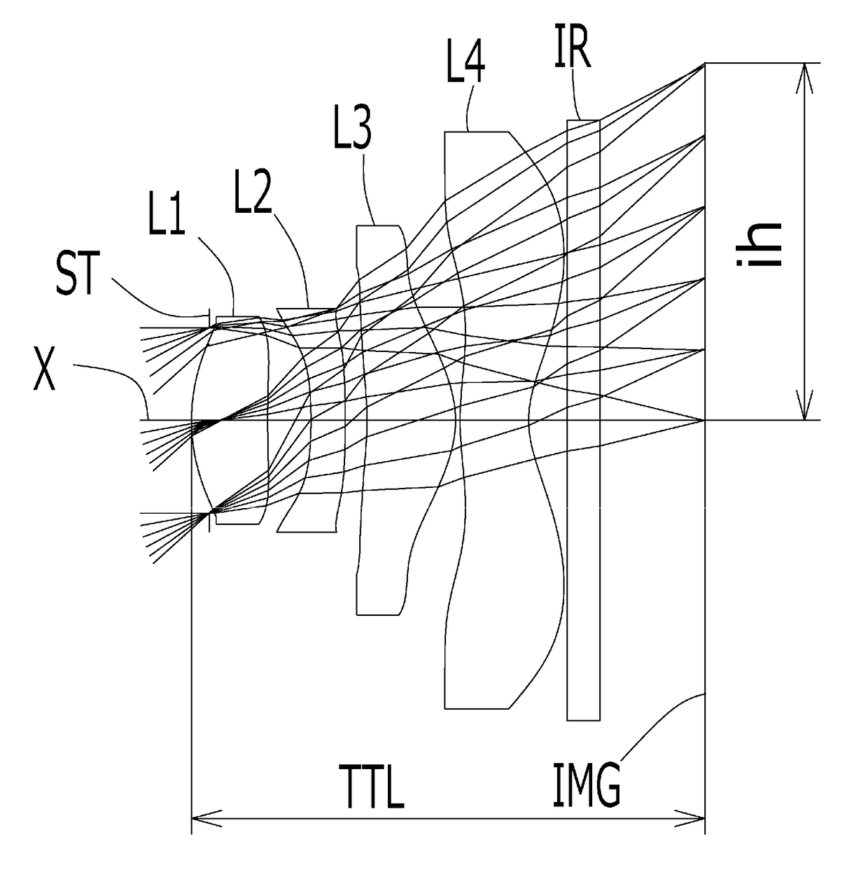
TABLE 1Unit [mm]f = 2.50Fno = 2.1ω (°) = 42ih = 2.29Surface DataSurfaceCurvatureSurfaceAbbeNumber iRadius rDistance dRefractiveNumber(Object)InfinityInfinityIndex Ndνd 1 (Stop)Infinity−0.150 2*1.104 (=r1)0.4281.544355.86 3*3.005 (=r2)0.332(=T1) 4*−7.371 (=r3) 0.200(=D2)1.650321.54 5*−28.109 (=r4) 0.191(=T2) 6*−1.931 (=r5) 0.600(=D3)1.534855.66 7*−0.697 (=r6) 0.036(=T3) 8*2.361 (=r7)0.4471.534855.66 9*0.660 (=r8)0.23210Infinity0.2101.516864.2011Infinity0.614ImageInfinityPlaneConstituent Lens DataLensStart SurfaceFocal Length122.9724−15.42361.7448−1.89Aspheric Surface dataSecondThirdFourthFifthSurfaceSurfaceSurfaceSurfacek0.000E+000.000E+000.000E+00−9.778E+00A42.672E−02−4.268E−03−3.875E−01−2.667E−02A6−1.127E−01−4.674E−01−1.485E+00−1.270E+00A85.258E−011.381E+003.420E+002.595E+00A10−8.809E−01−3.296E+00−6.712E+00−2.805E+00A120.000E+005.946E−017.042E+001.267E+00A140.000E+000.000E+000.000E+002.439E+00A160.000E+000.000E+000.000E+000.000E+00SixthSeventhEighthNinthSurfaceSurfaceSurfaceS...

example 2

[0090]

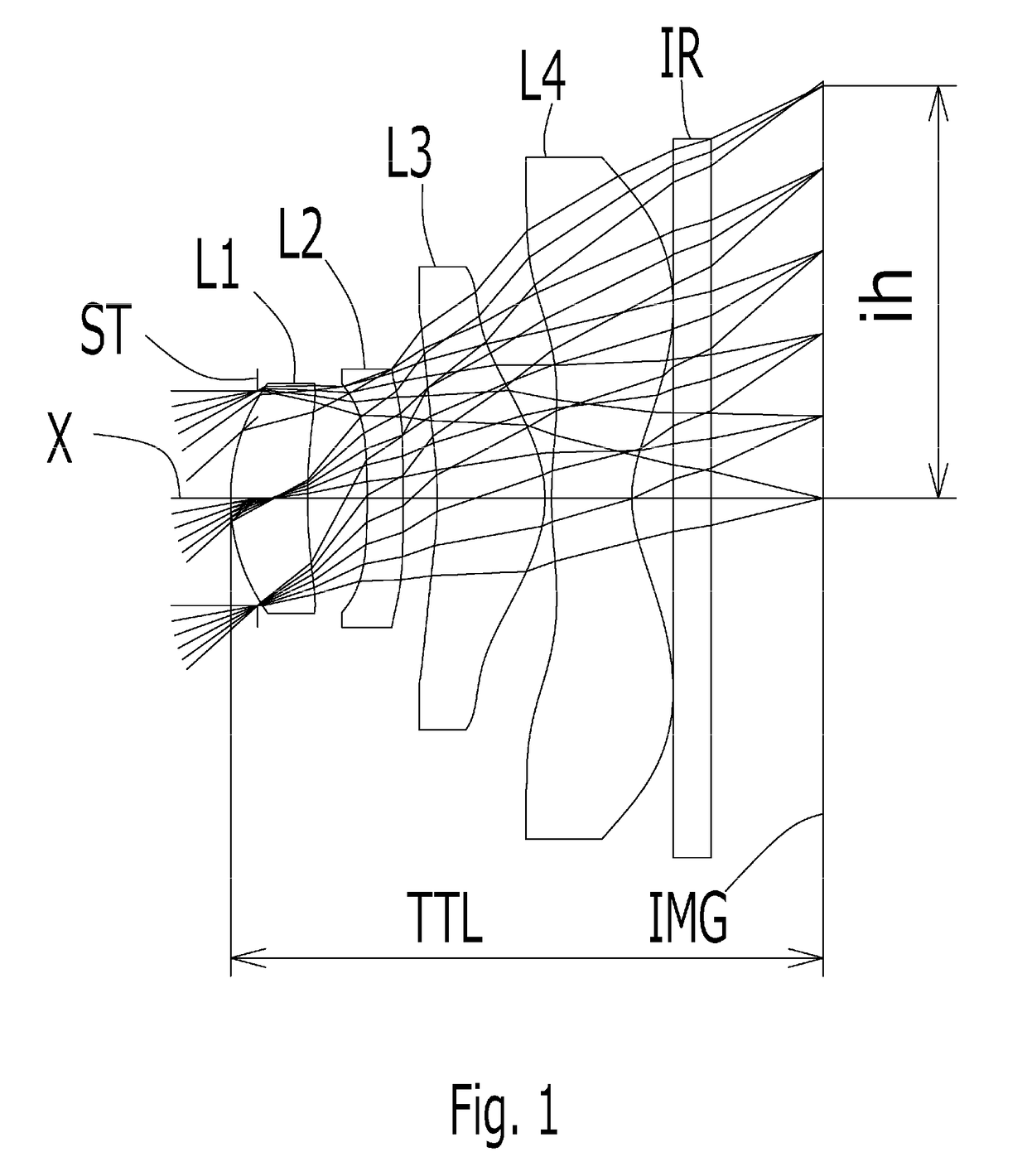
TABLE 2Unit [mm]f = 2.49Fno = 2.1ω (°) = 42ih = 2.29Surface DataSurfaceCurvatureSurfaceAbbeNumber iRadius rDistance dRefractiveNumber(Object)InfinityInfinityIndex Ndνd 1 (Stop)Infinity−0.113 2* 1.198 (=r1)0.4891.544355.86 3* 5.731 (=r2)0.279(=T1) 4*−2.910 (=r3)0.220(=D2)1.650321.54 5*−7.565 (=r4)0.140(=T2) 6*−1.977 (=r5)0.569(=D3)1.534855.66 7*−0.693 (=r6)0.030(=T3) 8* 1.977 (=r7)0.4401.534855.66 9* 0.625 (=r8)0.24810Infinity0.2101.516864.2011Infinity0.664Image PlaneInfinityConstituent Lens DataLensStart SurfaceFocal Length122.6824−7.41361.7348−1.92Aspheric Surface dataSecondThirdFourthFifthSurfaceSurfaceSurfaceSurfacek0.000E+000.000E+000.000E+00−9.778E+00A41.539E−02−2.500E−01−6.829E−015.805E−02A6−4.730E−019.864E−03−4.013E−01−2.370E+00A81.627E+00−2.204E+00−3.979E+007.204E+00A10−3.099E+002.885E+002.096E+01−1.272E+01A120.000E+00−1.261E+00−2.001E+011.911E+01A140.000E+000.000E+000.000E+00−1.214E+01A160.000E+000.000E+000.000E+000.000E+00SixthSeventhEighthNinthSurfaceSurfaceSurfaceS...

example 3

[0094]

TABLE 3Unit [mm]f = 2.49Fno = 2.1ω (°) = 42ih = 2.30Surface DataSurfaceCurvatureSurfaceAbbeNumber iRadius rDistance dRefractiveNumber(Object)InfinityInfinityIndex Ndνd 1 (Stop)Infinity−0.142 2*1.176 (=r1)0.4281.544355.86 3*3.913 (=r2)0.312(=T1) 4*−5.096 (=r3) 0.221(=D2)1.650321.54 5*22.954 (=r4) 0.180(=T2) 6*−3.620 (=r5) 0.645(=D3)1.534855.66 7*−0.655 (=r6) 0.052(=T3) 8*2.191 (=r7)0.3671.534855.66 9*0.570 (=r8)0.31310Infinity0.2101.516864.2011Infinity0.590Image PlaneInfinityConstituent Lens DataLensStart SurfaceFocal Length122.9324−6.39361.3948−1.56Aspheric Surface dataSecondThirdFourthFifthSurfaceSurfaceSurfaceSurfacek0.000E+000.000E+000.000E+006.357E+01A43.844E−03−9.705E−02−5.671E−01−2.374E−01A6−2.010E−01−4.258E−01−1.065E+00−6.236E−01A88.596E−014.119E−013.700E+001.897E+00A10−1.904E+00−1.982E+00−9.742E+00−2.771E+00A120.000E+005.995E−011.279E+013.163E+00A140.000E+000.000E+000.000E+00−3.500E−01A160.000E+000.000E+000.000E+000.000E+00SixthSeventhEighthNinthSurfaceSurfaceSurfaceSu...


PUM


Abstract

There is provided an imaging lens which is low-profile, has a small f-value, and obtains wide field of view which aberrations are properly corrected, in order from an object side to an image side, comprising a first lens having positive refractive power and a convex surface on an object side near an optical axis, a second lens having negative refractive power and a concave surface on the object side near the optical axis, a third lens having positive refractive power and a convex surface on the image side as a double-sided aspheric lens and a fourth lens having negative refractive power and a concave surface on an image side near the optical axis as a double-sided aspheric lens, wherein a conditional expression (1) below is satisfied:
8.5<ih/f<1.0  (1)
where f denotes the focal length of the overall optical system, and ih denotes maximum image height.

Description

[0001]The present application is based on and claims priority of Japanese patent application No. 2015-255116 filed on Dec. 25, 2015, the entire contents of which are hereby incorporated by reference.BACKGROUND OF THE INVENTIONField of the Invention[0002]The present invention relates to an imaging lens which forms an image of an object on a solid-state image sensor such as a CCD sensor or a C-MOS sensor used in a compact imaging device, and more particularly to an imaging lens which is built in an imaging device mounted in an increasingly compact and low-profile mobile terminal such as a mobile phone, smartphone, or PDA (Personal Digital Assistant), or a game console, or an information terminal such as a PC.Description of the Related Art[0003]In recent years, a market of a mobile terminal comprising an imaging device has been expanded. Almost mobile terminal has a camera function, and high-performance of the camera has been improved. As a smartphone, design of many products becomes l...

Claims


Application Information

Patent Timeline
IPC IPC(8): G02B13/00G02B9/34G02B13/18G02B13/22
CPCG02B13/004G02B13/18G02B13/22G02B9/34G02B13/06
Inventor YUZA, SHINGOKAMATA, KENICHI
Owner TOKYO VISIONARY OPTICS CO LTD
Why Eureka
Try Eureka