
System and method for material constitutive modeling

a technology of constitutive modeling and material, applied in the field of computer modeling, can solve the problems of increasing the amount of computing resources and complexity of the object model to be analysed, and achieve the effects of reducing the number of calculations and the amount of memory required, and improving processing accuracy and speed

Inactive Publication Date: 2017-11-16
SIEMENS PROD LIFECYCLE MANAGEMENT SOFTWARE INC
View PDF0 Cites 6 Cited by
  • Summary
  • Abstract
  • Description
  • Claims
  • Application Information

AI Technical Summary

Benefits of technology

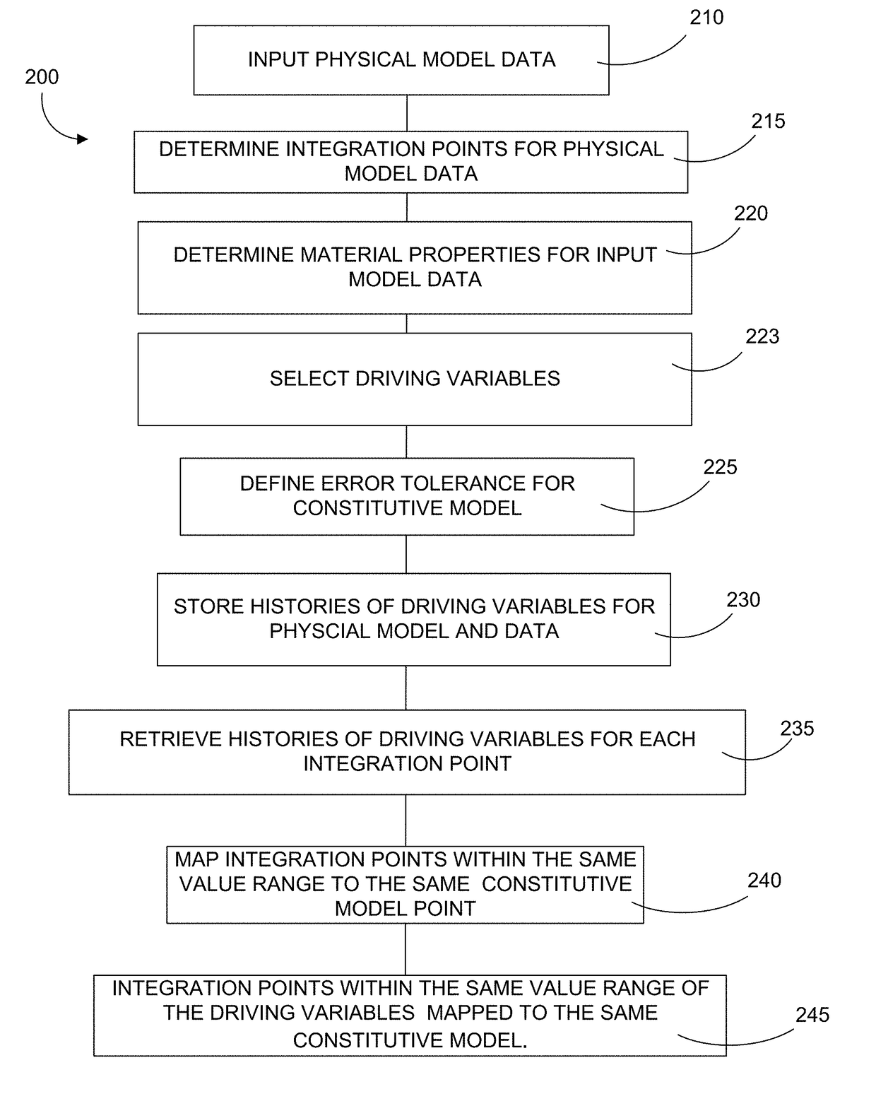
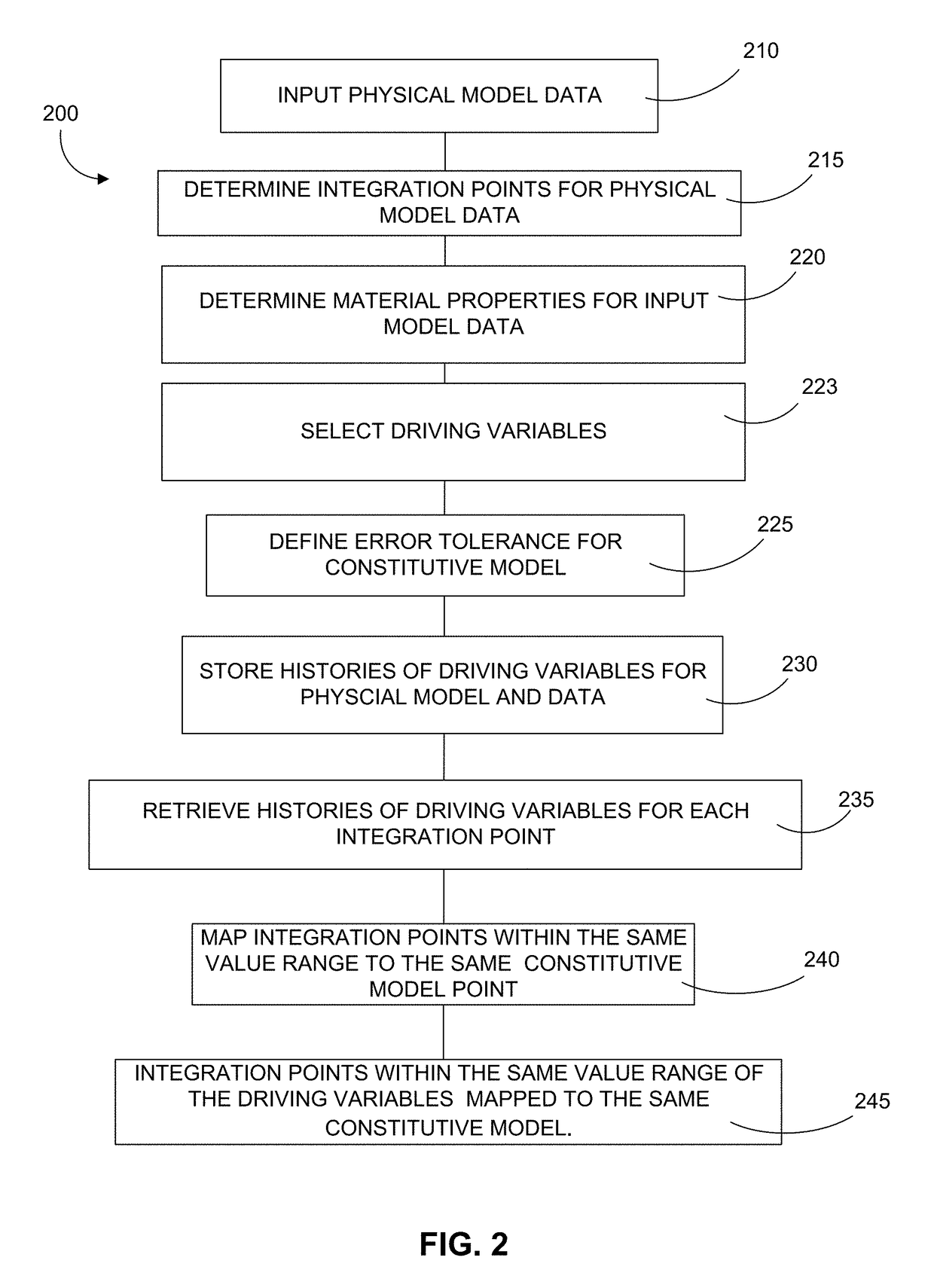
The present invention provides tools and methods to predict material behavior and minimize the computational resources needed for accurate simulations. These tools allow for efficient prediction of material behavior by reducing the number of calculations and amount of memory required. The invention also tracks the history of specific driving variables, optimizing the amount of data needed to model the entire element / object. The invention dynamically links material responses computed for each unique history of driving variables to each integration point and configurational model in the modeled element / object. The invention also offers a way to avoid repeated computations and memory usage for the same unique history of driving variables. Overall, the invention improves processing accuracy and speed for a variety of computing tasks and maximizes performance across available computational resources.

Problems solved by technology

Along with an increase in their use, the object models to be analyzed have become increasingly complex.
For large problems, this requires a lot of computing resources (i.e., memory, CPU processing time) because memory allocation and computations are unique for each and every integration point.

Method used


Image

  • System and method for material constitutive modeling
  • System and method for material constitutive modeling
  • System and method for material constitutive modeling

Examples


Embodiment Construction

[0028]Various inventive features are described below that can each be used independently of one another or in combination with other features. However, any single inventive feature may not address any of the problems discussed above or only address one of the problems discussed above. Further, one or more of the problems discussed above may not be fully addressed by any of the features described below. In the following discussion that addresses a number of embodiments and applications of the present invention, reference is made to the accompanying drawings that form a part hereof, and in which is shown by way of illustration specific embodiments in which the invention may be practiced. It is to be understood that other embodiments may be utilized and changes may be made without departing from the scope of the present invention.

[0029]At least portions of the functionalities or processes described herein can be implemented in suitable computer-executable instructions. The computer-exe...


PUM


Abstract

According to a preferred embodiment, the present invention provides a computing device and method to efficiently predict material behavior and to minimize the computational resources needed to obtain accurate simulations. According to a further preferred embodiment, the present invention tracks the history of driving variables for a section of a modeled element / object, for each material point or integration point or constitutive model. According to a further preferred embodiment, the present invention only maps unique histories of driving variables, within certain tolerance, to actual integration points' and / or constitutive models' data structure in order to optimize the amount of data needed to model the entire modeled element / object under determined boundary conditions. According to a further preferred embodiment, the present invention thereafter dynamically links the material response to each integration point and / or constitutive model in the modeled element / object. According to a further preferred embodiment, the present invention further balances the analysis work load across available computational resources to provide maximized performance. According to a further preferred embodiment, the present invention further reduces computational requirements through the use of databases to store / retrieve results obtained for a given history of driving variables and material definition.

Description

RELATED APPLICATIONS[0001]The present application claims priority to U.S. Provisional Application No. 62 / 334,069 filed May 10, 2016.FIELD OF INVENTION[0002]The present invention is related in general to computer modeling and, in particular, to a method for material constitutive modeling.BACKGROUND OF THE INVENTION[0003]Constitutive models describe the physical properties of a given material. In physics and engineering, a constitutive equation or constitutive relation is a relation between two physical quantities (especially kinetic quantities as related to kinematic quantities) that are specific to a material or substance, and which approximate the response of that material to external stimuli, usually as applied fields or forces. In recent years, it has become increasingly common to use constitutive models to simulate the physical motion of a design model using a computer. These models have wide use in heat conduction analysis, fluid analysis, structural analysis, electromagnetic f...

Claims


Application Information

Patent Timeline
IPC IPC(8): G06F17/50
CPCG06F17/5009G06F17/5018G06F2217/16G06F2111/10G06F30/23G06F30/20
Inventor SALES DE CASTRO, LEANDROVASCONCELOS DE SOUZA, FLAVIO
Owner SIEMENS PROD LIFECYCLE MANAGEMENT SOFTWARE INC
Learn More