Hybrid vehicle

a hybrid vehicle and hybrid technology, applied in the field of hybrid vehicles, can solve the problems of insufficient driving force, driver discomfort in not acquiring such a feeling of a change in speed, and inability to drive, so as to prevent the insufficient driving force from becoming insufficient, improve the driving feeling, and increase the target rotation speed

Inactive Publication Date: 2017-11-23
TOYOTA JIDOSHA KK
View PDF0 Cites 5 Cited by
  • Summary
  • Abstract
  • Description
  • Claims
  • Application Information

AI Technical Summary

Benefits of technology

[0007]According to the hybrid vehicle of the aspect, the target rotation speed of the engine is set on the basis of the depression amount of the accelerator pedal, the vehicle speed, and a shift stage such that the target rotation speed of the engine increases as the depression amount of the accelerator pedal increases. The upper-limit driving force is set as a driving force when the maximum power capable of being output from the engine when the engine operates at the target rotation speed is output to the drive shaft, and the engine, the first motor, and the second motor are controlled such that the engine operates at the target rotation speed and the smaller driving force of the upper-limit driving force and the required driving force is output to the drive shaft. Since the target rotation speed of the engine is set on the basis of the depression amount of the accelerator pedal, the vehicle speed, and the shift stage, it is possible to operate the engine at the engine rotation speed based on the vehicle speed even when a driver steps on the accelerator pedal and to give a better driving feeling to the driver in comparison with a case in which the engine rotation speed increases rapidly before the vehicle speed increases. When the shift stage is changed (shifted) by the driver's stepping on the accelerator pedal, the target rotation speed changes with a change in the shift stage and it is thus possible to give a feeling of a change in speed to the driver. Since the target rotation speed is set to have an increasing trend as the depression amount of the accelerator pedal increases, it is possible to set a higher target rotation speed in comparison with a case in which the target rotation speed is set regardless of the depression amount of the accelerator pedal and to prevent the driving force from becoming insufficient by increasing the power capable of being output from the engine. As a result, it is possible to give a better driving feeling to a driver and to prevent a driving force from becoming insufficient.
[0008]In the hybrid vehicle according to the aspect, the electronic control unit may be configured to set a rotation speed base value of the engine on the basis of the vehicle speed and the shift stage, the electronic control unit may be configured to set a rotation speed correction value such that the rotation speed correction value increases as the depression amount of the accelerator pedal increases, and the electronic control unit may be configured to set the target rotation speed by correcting the rotation speed base value using the rotation speed correction value. According to the hybrid vehicle of the aspect, it is possible to set the rotation speed base value such that a better driving feeling is given to a driver and to set the rotation speed correction value such that the driving force is prevented from becoming insufficient.
[0009]In the hybrid vehicle according to the aspect, the electronic control unit may be configured to set the rotation speed correction value such that the rotation speed correction value is greater when the shift stage is a high-speed level than when the shift stage is a low-speed level. At a low-speed shift stage, since the hybrid vehicle travels at a relatively low speed, an increase in the power output from the engine due to the depression amount of the accelerator pedal is small. On the other hand, at a high-speed shift stage, since the hybrid vehicle travels at a relatively high speed, an increase in the power output from the engine due to the depression amount of the accelerator pedal is large. Since the power output from the engine is expressed as a product of the rotation speed and the torque, the increase in the power output from the engine is achieved by an increase in the rotation speed or an increase in the torque. Accordingly, when the increase in the output power is large, it is effective to increase the rotation speed as well as to increase the torque. According to the hybrid vehicle of the aspect, it is possible to cope with an increase in output power at a high-speed shift stage by setting a larger rotation speed correction value at a high-speed shift stage than at a low-speed shift stage.
[0010]In the hybrid vehicle according to the aspect, the electronic control unit may be configured to set the rotation speed correction value such that the rotation speed correction value is greater when the rotation speed of the engine is relatively low than when the rotation speed of the engine is relatively high. As described above, the power output from the engine is expressed as a product of the rotation speed and the torque. Accordingly, when the torque increases but the rotation speed is low, the power output from the engine is slightly greater than that when the rotation speed is high. According to the hybrid vehicle of the aspect, it is possible to cope with a larger increase in the output power even when the rotation speed is low, by setting a large rotation speed correction value when the rotation speed is low.
[0011]In the hybrid vehicle according to the aspect, the electronic control unit may be configured to set the target rotation speed such that a rate of change of the target rotation speed decreases when a temperature of the battery decreases when the rotation speed of the engine increases by setting the rotation speed correction value. In a transition period in which the rotation speed of the engine is increasing, the power required for increasing the rotation speed of the engine and an insufficient power for driving power need to be covered with an output from the battery. When the temperature of the battery is low, the output of the battery is small. Accordingly, the power required for increasing the rotation speed of the engine and the insufficient power for driving power are not covered and the driving power becomes insufficient. According to the hybrid vehicle of the aspect, it is possible to prevent the driving power from becoming insufficient by slowly increasing the rotation speed of the engine when the temperature of the battery is low.

Problems solved by technology

Accordingly, when only the engine rotation speed increases rapidly before the vehicle speed increases, the driver may feel discomfort in terms of the driving feeling.
In this case, since the driver generally has a feeling of a change in speed in which the rotation speed of the engine decreases due to the upshift of the stepped gearshift as a driving feeling, the driver may feel discomfort in not acquiring such a feeling of a change in speed.
However, since the engine can output only a torque corresponding to the rotation speed thereof, the driving force may be insufficient.
Such a problem is true when a virtual speed level shift is performed in a hybrid vehicle not including a stepped gearshift.
In a transition period in which the rotation speed of the engine is increasing, the power required for increasing the rotation speed of the engine and an insufficient power for driving power need to be covered with an output from the battery.
Accordingly, the power required for increasing the rotation speed of the engine and the insufficient power for driving power are not covered and the driving power becomes insufficient.

Method used


Image

  • Hybrid vehicle
  • Hybrid vehicle
  • Hybrid vehicle

Examples


first embodiment

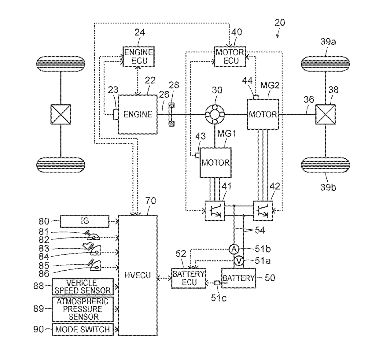
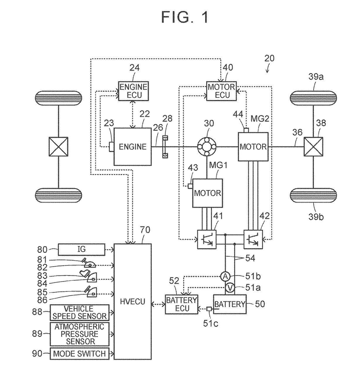
[0043]The hybrid vehicle 20 having the above-mentioned configuration travels in any one of a plurality of driving modes including a hybrid driving (HV driving) mode and an electrical driving (EV driving) mode. Here, the HV driving mode is a mode in which the vehicle travels using power from the engine 22 and power from the motors MG1 and MG2 while operating the engine 22. The EV driving mode is a mode in which the vehicle travels using power from the motor MG2 without operating the engine 22.

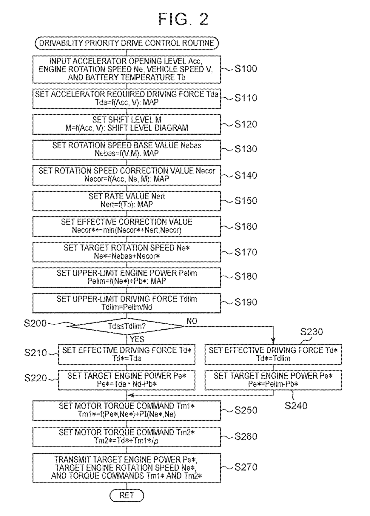
[0044]The operation of the hybrid vehicle 20 having the above-mentioned configuration, particularly, the operation when a driving feeling priority mode is selected by the mode switch 90, will be described below. FIG. 2 is a flowchart illustrating an example of a drivability priority drive control routine which is performed by the HVECU 70 when the driving feeling priority mode is selected and the shift position SP upshifts to the driving position (D position). This routine is repeatedly perform...

second embodiment

[0079]In the hybrid vehicle 120 when the shift position is the D position in the driving feeling priority mode, the drivability priority drive control routine illustrated in FIG. 16 is performed. The drivability priority drive control routine illustrated in FIG. 16 is the same as the drivability priority drive control routine illustrated in FIG. 2, except for Step S120C of setting an actual shift stage Ma as well as the shift stage M, Step S260C of setting the torque command Tm2* of the motor MG2 using a gear ratio Gr of the actual shift stages Ma of the gearshift 130, and step S270C of transmitting the actual shift stage Ma to the gearshift 130 when transmitting the target engine power Pe* or the target engine rotation speed Ne*. Accordingly, the same processes in the drivability priority drive control routine illustrated in FIG. 16 as in the drivability priority drive control routine illustrated in FIG. 2 are referenced by the same step numbers. The drivability priority drive con...


PUM


Abstract

A hybrid vehicle includes an engine, a first motor, a planetary gear mechanism, a second motor, a battery, and an electronic control unit. The electronic control unit is configured to: control the engine, the first motor, and the second motor such that the hybrid vehicle travels using a required driving force; set a target rotation speed on a basis of the depression amount of the accelerator pedal, the vehicle speed, and a shift stage such that the target rotation speed of the engine increases as the depression amount of the accelerator pedal increases; set an upper-limit driving force; and control the engine, the first motor, and the second motor such that the engine operates at the target rotation speed and the smaller driving force of the upper-limit driving force and the required driving force is output to the drive shaft.

Description

CROSS-REFERENCE TO RELATED APPLICATIONS[0001]This application claims priority to Japanese Patent Application No. 2016-099384 filed on May 18, 2016, the entire contents of which are hereby incorporated by reference.BACKGROUND1. Technical Field[0002]The present disclosure relates to a hybrid vehicle.2. Description of Related Art[0003]In the related art, a hybrid vehicle in which a rotary element, which is connected to a second motor, of a planetary gear mechanism of which three rotary elements are connected to an engine, a first motor, and the second motor is connected to a drive shaft connected to vehicle wheels via a stepped gearshift has been proposed (for example, see Japanese Patent Application Publication No. 2014-144659 (JP 2014-144659 A)). Driving of such a vehicle is basically controlled as follows. First, a required driving force is set on the basis of a depression amount of an accelerator pedal by a driver and a vehicle speed, and the required driving force is multiplied by...

Claims


Application Information

Patent Timeline
Patent Type & Authority Applications(United States)
IPC IPC(8): B60W10/08B60W20/00B60K6/365B60K6/445B60K6/48B60L50/16B60W10/04
CPCB60W10/08B60K6/365B60K6/48B60K6/445B60W10/04B60W20/00B60K6/547B60W10/06B60W20/10B60W2510/0638B60W2540/10B60W2540/16B60W2710/0644B60W2710/0677B60W2710/083B60W10/11B60W20/30B60W30/1882B60W50/10B60W2510/244B60W2520/10B60W2710/0666Y02T10/62Y02T10/72
Inventor KATO, SHUNYASUGAI, MASAYA
Owner TOYOTA JIDOSHA KK
Why Eureka
Try Eureka