Pneumatic tire

a technology of pneumatic tires and spherical plates, which is applied in the direction of heavy-duty vehicles, vehicle components, vehicles, etc., can solve the problems of uneven wear, damage to the bottom of the groove, and the groove b>20/b> may not effectively function to reduce uneven wear, so as to reduce uneven wear and improve durability without reducing productivity. , the effect of reducing the effect of wear

Active Publication Date: 2017-11-30
SUMITOMO RUBBER IND LTD
View PDF10 Cites 0 Cited by
  • Summary
  • Abstract
  • Description
  • Claims
  • Application Information

AI Technical Summary

Benefits of technology

[0012]In the pneumatic tire according to the present invention, the sidewall stacked on the cap layer prevents the base layer from having a protrusion. In the tire, the thickness of the cap layer is appropriately assured in the groove portion that sections the rib disposed on the outer side in the axial direction, that is, a shoulder rib into the body portion and the side portion. In the tire, damage is less likely to occur at the groove bottom portion. In the tire, the groove is maintained, whereby an effect of reducing uneven wear by providing the groove is exhibited as expected. In addition, a new component need not be added and the groove need not be formed into a special shape in order to prevent the groove from being damaged. The tire has an improved durability without reducing productivity. According to the present invention, the pneumatic tire having an improved durability without reducing productivity can be obtained.

Problems solved by technology

Therefore, a problem arises that wear is likely to develop in the shoulder portions.
Meanwhile, it is also known that damage is likely to occur at the bottom of the groove 20, and the groove 20 may not effectively function to reduce the uneven wear depending on the degree of the damage.
In this technique, although durability can be improved, productivity is likely to be reduced.
Since the groove 20 has the special shape, cost may be increased not only for production of the mold but also for maintenance and management or the like.

Method used


Image

  • Pneumatic tire
  • Pneumatic tire
  • Pneumatic tire

Examples


example 1

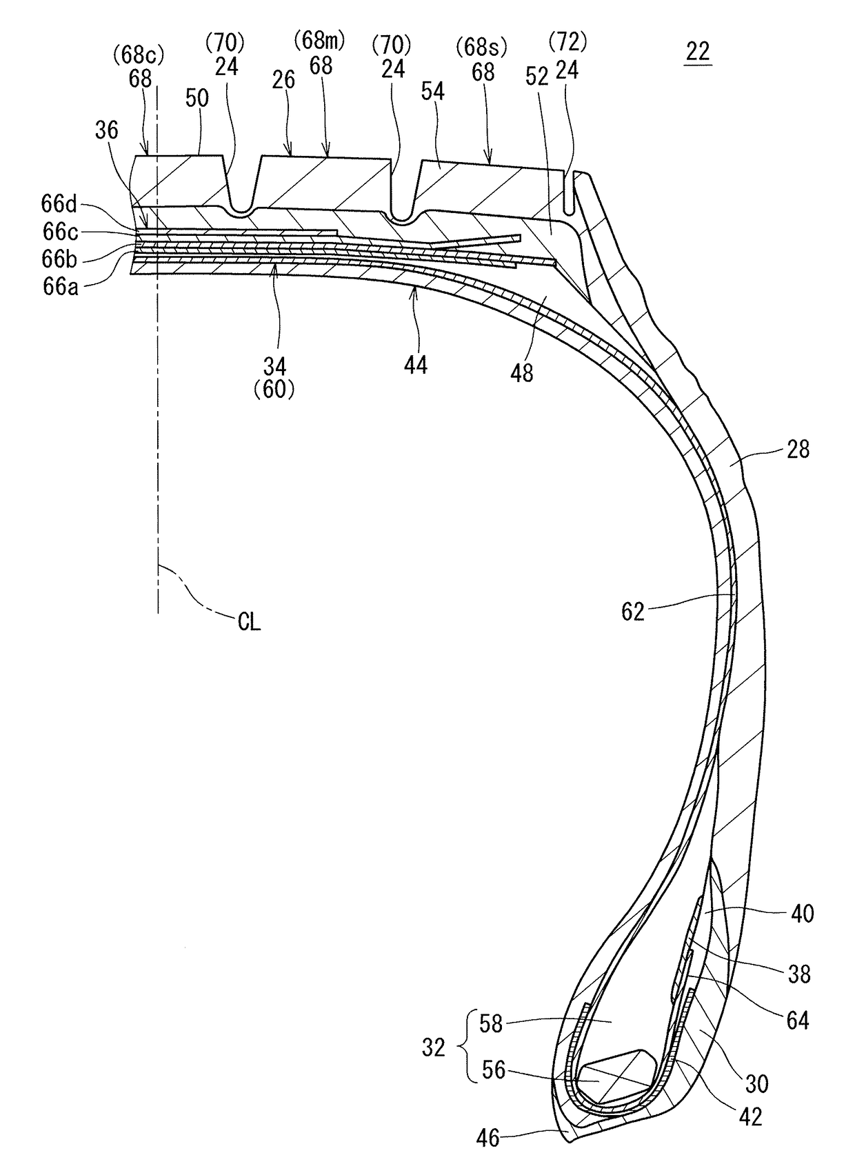
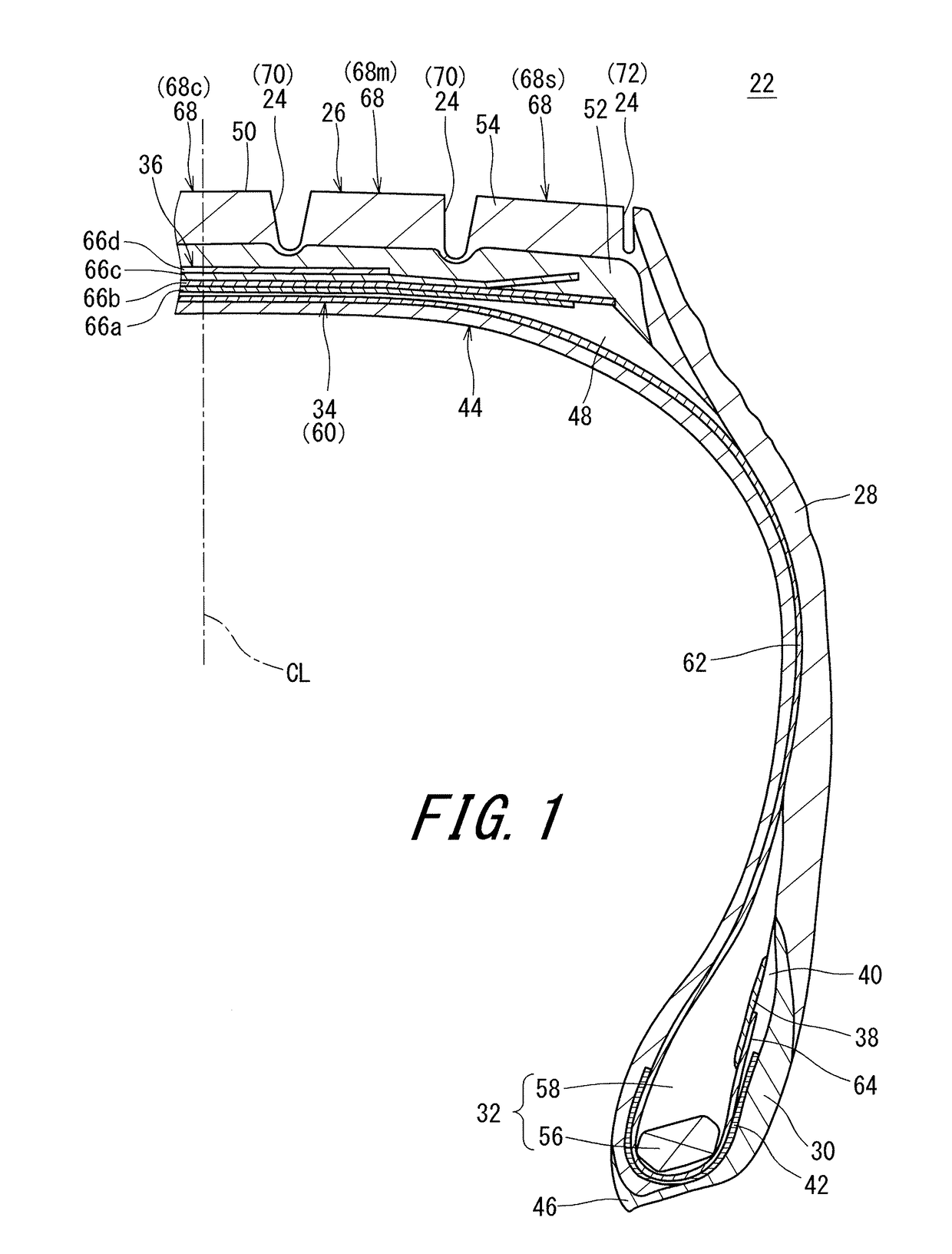
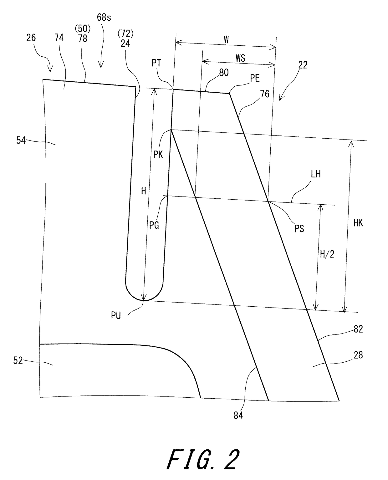
[0070]A tire having the basic structure shown in FIGS. 1 to 2 and the specifications indicated below in Table 1 was produced (In the table, “Example 1” is abbreviated as “Ex. 1”). The size of the tire was 295 / 75R22.5. In shoulder ribs of the tire, each side portion was formed by a cap layer and a sidewall, and the sidewall was stacked on the cap layer. A ratio (W / H) of the width W of the side portion to the height H of the side portion was 0.25. The ratio (HK / H) of the height HK from the bottom of a sub-groove to the end of the boundary between the sidewall and the cap layer relative to the height H of the side portion was 0.60. In Example 1, a component was not added and the groove was not formed into a special shape in order to prevent the sub-groove from being damaged. This is indicated in Table 1 as “-” in the cells for “shape” and “material”.

examples 2 to 11

[0073]Tires of examples 2 to 11 were each obtained in the same manner as in example 1 except that the ratio (W / H) and the ratio (HK / H) were as indicated below in Tables 1 to 3.

example 12

[0074]A tire of example 12 was obtained in the same manner as in example 1 except that the end of the boundary between a sidewall and a cap layer was disposed between the inner side end PT and the outer side end PE of the top surface of a side portion.

[0075][Evaluation for Performance]

[0076]Each tire was mounted on a normal rim, and inflated with air to an internal pressure of 830 kPa. The tires were scratch-mounted to front wheels and rear wheels of a truck (10 tons), and the truck was caused to run on a general public road (expressway and general road) in a fully loaded state at a speed of 80 km / h. When the truck had run fifty thousand miles, the tires were collected, and occurrence of the uneven wear in the tires was confirmed, and the tires were each disassembled, and occurrence of disarrangement and damage in the base layers at the sub-groove portions was confirmed. The results are indicated below in Tables 1 to 3 as indexes based on the grading below. The greater the numerical...


PUM


Abstract

A tire 22 includes a plurality of ribs 68 aligned in an axial direction. A rib 68s, among the plurality of ribs 68, disposed on an outer side in the axial direction is sectioned into a body portion 74 and a side portion 76 by a groove 72 that extends in a circumferential direction. The tire 22 includes a tread 26 and a pair of sidewalls 28. The sidewalls 28 extend almost inward from ends, respectively, of the tread 26 in a radial direction. The tread 26 includes a base layer 52, and a cap layer 54 disposed outward of the base layer 52 in the radial direction. The side portion 76 is formed by the cap layer 54 and a corresponding one of the sidewalls 28. The sidewall 28 is stacked on the cap layer 54 in the side portion 76.

Description

[0001]This application claims priority on Patent Application No. 2016-108044 filed in JAPAN on May 31, 2016. The entire contents of this Japanese Patent Application are hereby incorporated by reference.BACKGROUND OF THE INVENTIONField of the Invention[0002]The present invention relates to pneumatic tires. More specifically, the present invention relates to pneumatic tires having narrow grooves formed in shoulders.Description of the Related Art[0003]FIG. 3 shows a shoulder rib 4 portion (also referred to as a shoulder portion) of a conventional tire 2. As shown in FIG. 3, the tire 2 includes a tread 6 and sidewalls 8. The sidewalls 8 extend almost inward from the tread 6 in the radial direction. In the tire 2, the sidewalls 8 are layered on the tread 6. Such a structure is also referred to as an SOT (Sidewall on Tread) structure. In the SOT structure, an end PK of each sidewall 8 is positioned on a side surface 12 that extends almost inward from an end PE of a tread surface 10 in the...

Claims


Application Information

Patent Timeline
Patent Type & Authority Applications(United States)
IPC IPC(8): B60C11/00B60C13/00B60C11/01
CPCB60C11/005B60C11/01B60C13/00B60C2011/013B60C2200/06B60C2011/016B60C11/0041B60C2011/039
Inventor ATAKE, IKUO
Owner SUMITOMO RUBBER IND LTD
Why Eureka
Try Eureka