Turbocharger engine

a turbocharger and engine technology, applied in the direction of combustion engines, combustion air/fuel air treatment, combustion feed systems, etc., can solve the problems of difficult to reduce intake resistance, and achieve the effect of improving supercharging efficiency and reducing intake resistan

Inactive Publication Date: 2017-11-30
MAZDA MOTOR CORP
View PDF2 Cites 4 Cited by
  • Summary
  • Abstract
  • Description
  • Claims
  • Application Information

AI Technical Summary

Benefits of technology

[0005]An object of the present invention is to provide a turbocharger engine provided with a turbocharger including a large turbo unit and a small turbo unit, which enables to reduce an intake resistance and to improve supercharging efficiency.

Problems solved by technology

Therefore, it may be difficult to reduce an intake resistance.

Method used


Image

  • Turbocharger engine
  • Turbocharger engine
  • Turbocharger engine

Examples


Embodiment Construction

Schematic Configuration of Engine

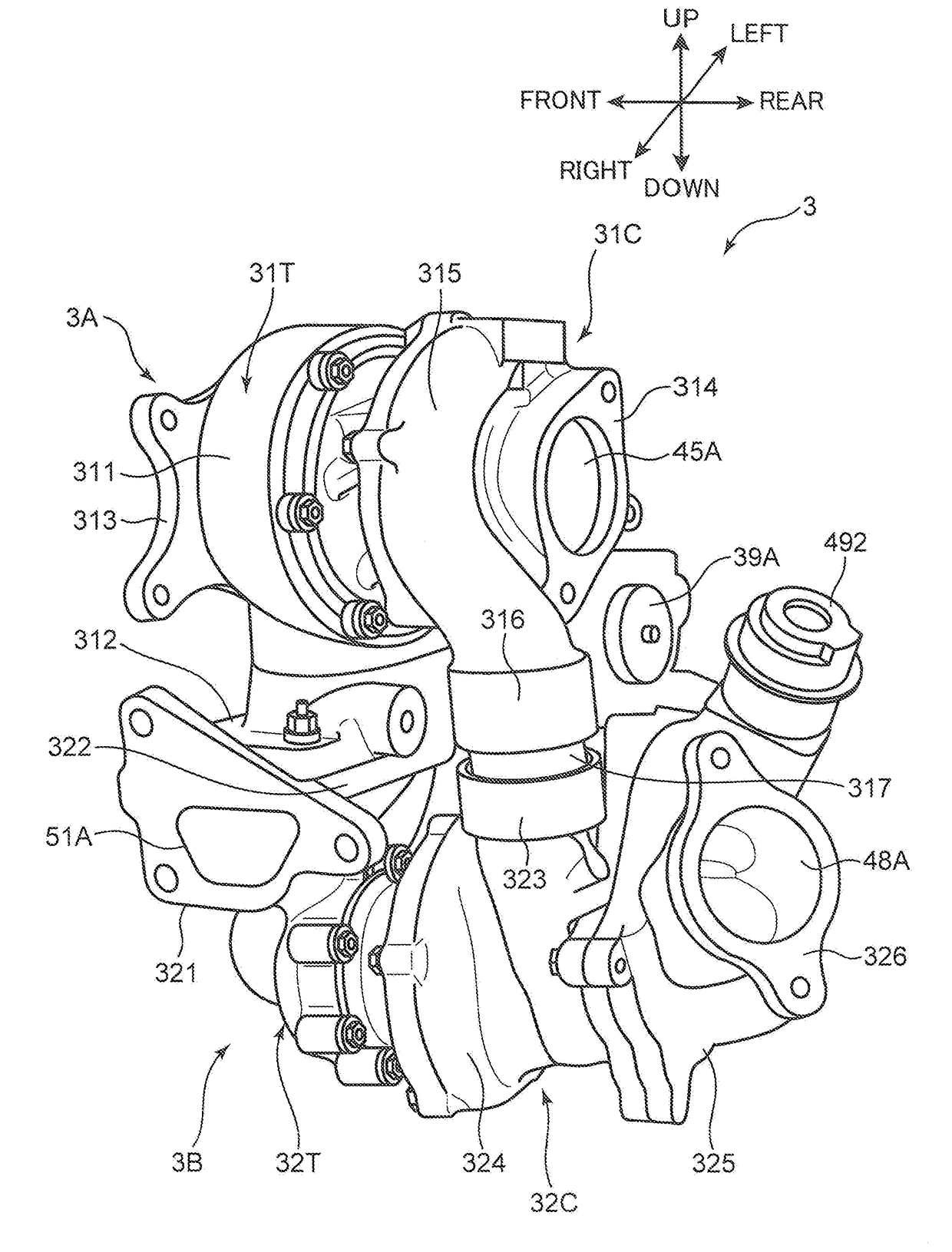
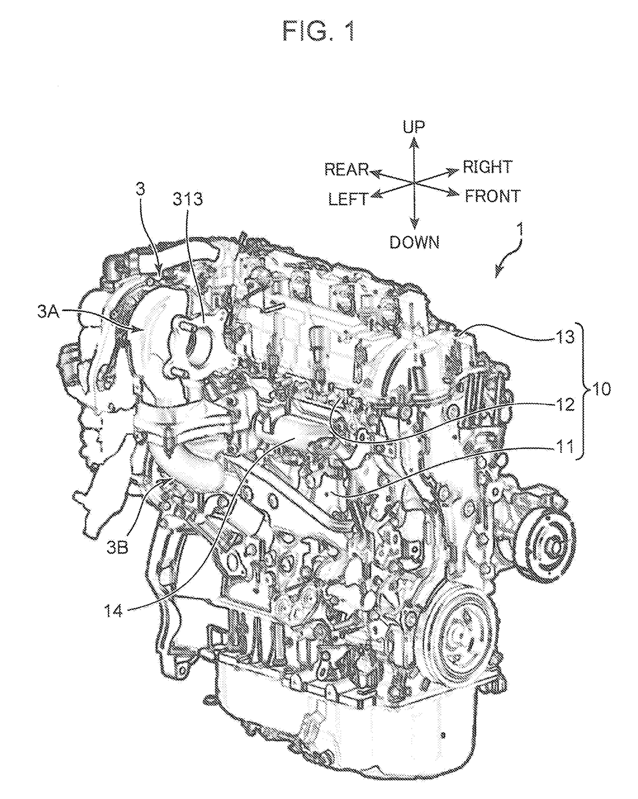
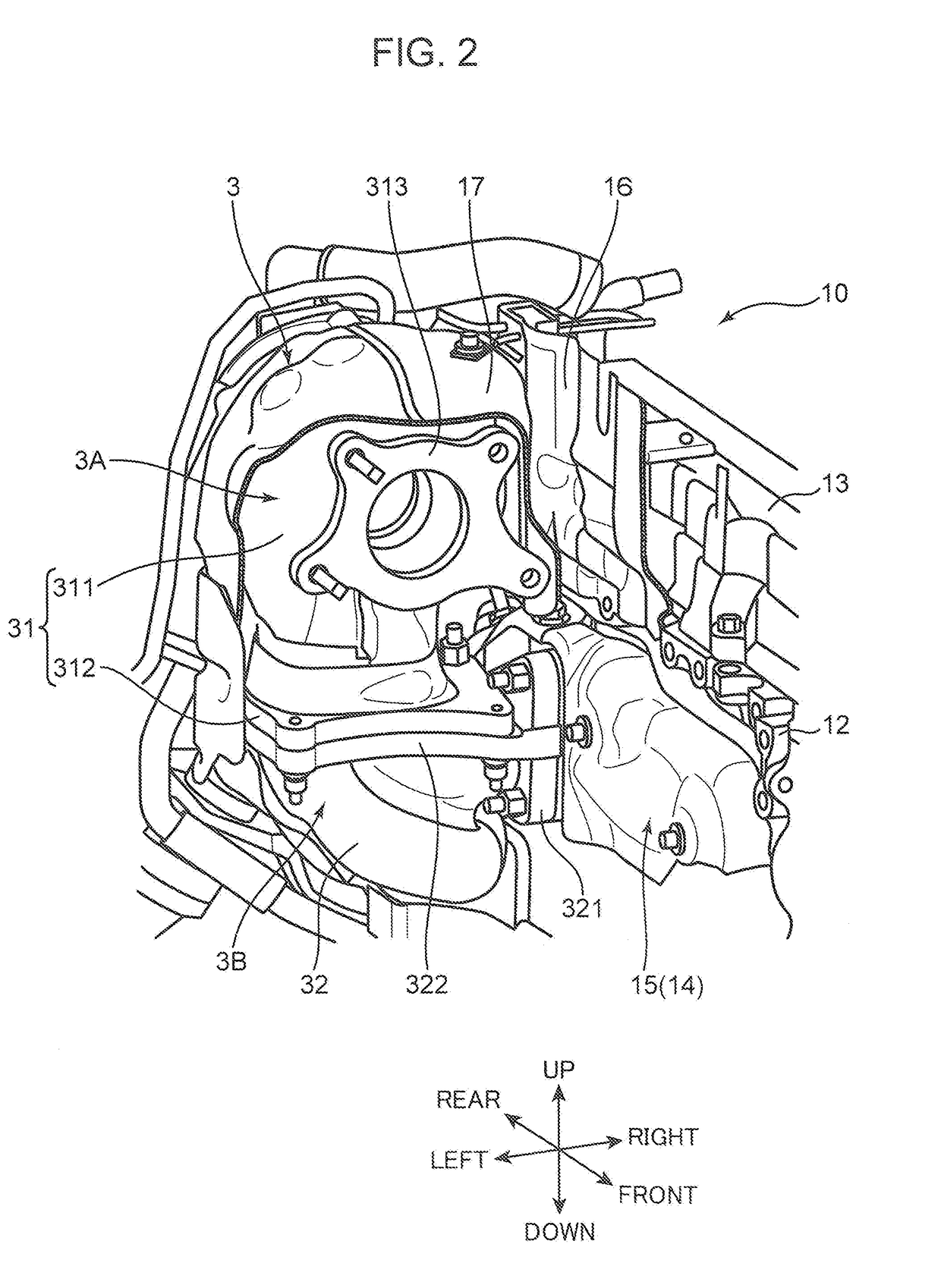
[0024]In the following, a turbocharger engine according to an embodiment of the present invention is described in detail based on the drawings. First of all, a schematic configuration of the engine is described. FIG. 1 is a perspective view of a turbocharger engine 1 according to the embodiment of the present invention. FIG. 2 is a partially cutaway perspective view illustrating a turbocharger 3 in the engine 1. In FIG. 1, FIG. 2, and the other drawings, a front direction, a rear direction, a left direction, a right direction, an upper direction, and a lower direction are indicated. This is for the sake of explanation, and does not necessarily indicate actual directions.

[0025]The turbocharger engine 1 includes a multi-cylinder engine body 10, an exhaust manifold 14 connected to a left surface of the engine body 10, an intake manifold 18 (see FIG. 8), and the turbocharger 3 disposed adjacent to the left side of the engine body 10. Although illustratio...


PUM


Abstract

A turbocharger engine includes an engine body and a turbocharger. The turbocharger includes a large turbo unit having a large turbine chamber, a large compressor chamber, and a large turbine shaft extending between the two chambers; and a small turbo unit having a small turbine chamber, a small compressor chamber, and a small turbine shaft extending between the two chambers. The large compressor chamber is disposed upstream of the small compressor chamber in an intake passage. A large turbo axis and a small turbo axis are disposed to extend generally in the same direction as an engine output axis. The large turbo unit is disposed such that the large turbo axis is non parallel to the engine output axis, and a large-compressor-chamber-side portion of the large turbo axis is closer to the engine output axis than a large-turbine-chamber-side portion thereof in a plan view in an axis direction of the cylinder.

Description

TECHNICAL FIELD[0001]The present invention relates to a turbocharger engine provided with a turbocharger including two independent turbo units in an engine body.BACKGROUND ART[0002]In a turbocharger engine, a turbocharger configured to supercharge intake air by using exhaust energy of an engine is mounted adjacent to a side wall of an engine body. An exhaust passage and an intake passage are formed in a housing of the turbocharger. A turbine chamber configured to accommodate a turbine communicates with the exhaust passage. A compressor chamber configured to accommodate a compressor impeller communicates with the intake passage. Exhaust air is supplied to the exhaust passage from the engine body, and intake air to be supplied to the engine body flows through the intake passage. The turbine is rotated around a turbine shaft by exhaust air to rotate the compressor impeller in the compressor chamber, which is connected to the turbine shaft to supercharge intake air.[0003]Conventionally,...

Claims


Application Information

Patent Timeline
Patent Type & Authority Applications(United States)
IPC IPC(8): F02B37/013F02B37/00F02B75/20F02M35/10
CPCF02B37/013F02B75/20F02M35/10157F02B37/004F02B37/00F02B39/00F02B67/10Y02T10/12
Inventor NIWA, YASUSHISUMIMOTO, HIROSHINAKAJIMA, MITSUHIRO
Owner MAZDA MOTOR CORP
Why Eureka
Try Eureka