Magnetically Hinged Overrunning Clutch

a magnetic hinged and overrunning technology, applied in the field of engineering, can solve the problems of difficult assembly, difficult maintenance, difficult manufacturing, etc., and achieve the effect of looser tolerances, simple and effective overrunning, and avoiding the complexity of mechanical springing of the sprags

Inactive Publication Date: 2017-11-30
ROSSER SHEREE BERMAN
View PDF0 Cites 2 Cited by
  • Summary
  • Abstract
  • Description
  • Claims
  • Application Information

AI Technical Summary

Benefits of technology

[0022]It is an object of the present invention to provide a simple, effective and robust overrunning clutch that avoids the complexity of mechanical springing of the sprags.
[0023]It is another object of the present invention to provide an overrunning clutch that can be manufactured with looser tolerances and from a greater range of materials than conventionally mechanically sprung sprag overrunning clutches.
[0024]Yet another object of the present invention is to provide inexpensive, but highly effective, overrunning clutches that have both rapid uptake and low overrunning loss, or friction, and are easy to design, easy to manufacture, easy to assemble and easy to maintain.

Problems solved by technology

The technical problem of providing an effective overrunning clutch, i.e., a coupling between rotating shafts that allows motion between the shafts when a first shaft is rotating faster than a second, but locks the shafts for transmission of torque when the second shaft is rotating faster than the first, is a well-known problem inherent in the technical field of general engineering.
However, most of the known designs are either constrained by a tradeoff between the maximum torque that can be transmitted and the speed of engagement of the clutch, or between the maximum torque and the amount of free-wheeling friction.
Moreover, existing high quality overrunning clutches tend to require mechanical springing of the elements which can make them difficult to manufacture, difficult to assemble and difficult to maintain.

Method used


Image

  • Magnetically Hinged Overrunning Clutch
  • Magnetically Hinged Overrunning Clutch
  • Magnetically Hinged Overrunning Clutch

Examples


Embodiment Construction

[0030]The preferred embodiments of the present invention will now be described in more detail with reference to the drawings in which identical elements in the various figures are, as far as possible, identified with the same reference numerals. These embodiments are provided by way of explanation of the present invention, which is not, however, intended to be limited thereto. Those of ordinary skill in the art may appreciate upon reading the present specification and viewing the present drawings that various modifications and variations may be made thereto without departing from the spirit of the invention.

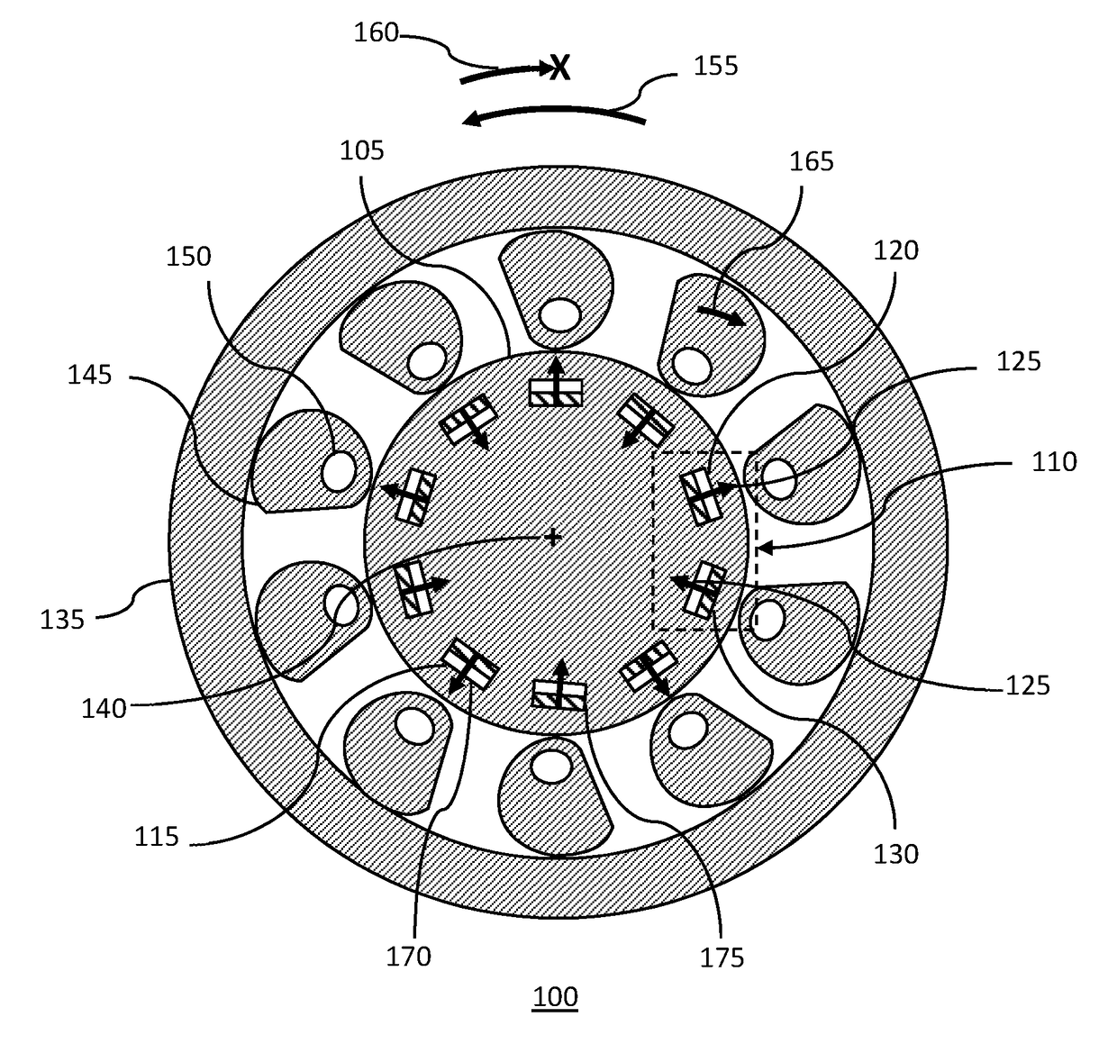
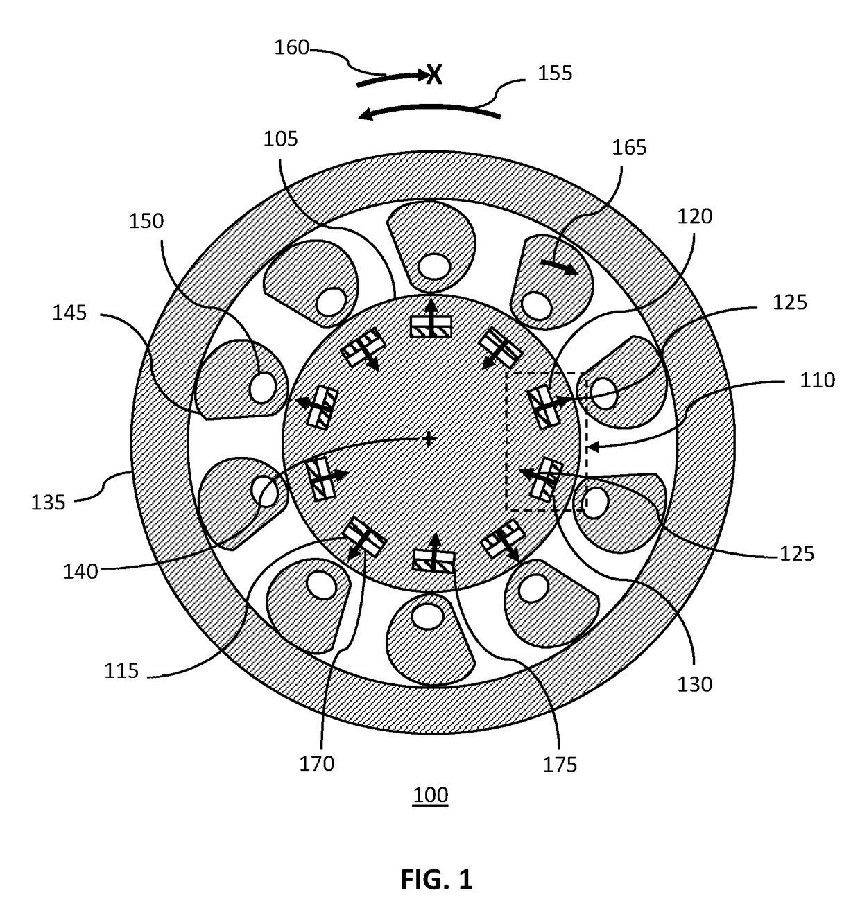
[0031]FIG. 1 shows a schematic cross-section of one embodiment of a magnetically hinged, overrunning clutch of the present invention.

[0032]The magnetically hinged, overrunning clutch 100 may consist of a first, or inner, shaft 105 co-axially located within a second, or outer, shaft 135, i.e., they may both have their axis of rotation 140 on a common line. A number of sprags 145 m...


PUM


Abstract

A magnetically hinged, overrunning clutch is disclosed. Sprags containing rare-earth permanent magnets, and arranged in pairs of opposite magnetic orientation, are located within the gap between the inner surface of a hollow, circularly cylindrical shaft and the external surface of a smaller diameter, second circularly cylindrical shaft. Pairs of rare-earth permanent magnets encircling the second cylindrical shaft are located at, or just beneath, the surface of the shaft and are arranged in pairs having alternating magnetic orientation. The sprags are cylinders having a pseudo-spiral cross-section and are sized, and the ferromagnetic region located, such that when the sprags are attracted to the shaft-magnets, the first shaft may be rotated with respect to the second shaft in a first, overrunning direction of rotation, but the first shaft does not rotate with respect to the second shaft in an opposite, or lock-up direction.

Description

CROSS-REFERENCE TO RELATED APPLICATIONS[0001]This application claims priority to U.S. Patent Application Ser. No. 62 / 343,044 filed on May 30, 2016, U.S. Patent Application Ser. No. 62 / 439,221 filed on Dec. 27, 2016 and to U.S. Patent Application Ser. No. 62 / 463,679 filed on Feb. 26, 2017 the contents of all of which are hereby fully incorporated herein by reference.BACKGROUND OF THE INVENTION(1) Field of the Invention[0002]The present invention is directed to the technical field of engineering, particularly to overrunning clutches, and more particularly, to magnetically hinged overrunning clutches.(2) Description of the Related Art[0003]The technical problem of providing an effective overrunning clutch, i.e., a coupling between rotating shafts that allows motion between the shafts when a first shaft is rotating faster than a second, but locks the shafts for transmission of torque when the second shaft is rotating faster than the first, is a well-known problem inherent in the technic...

Claims


Application Information

Patent Timeline
Patent Type & Authority Applications(United States)
IPC IPC(8): F16D41/07F16D27/01F16D27/02F16D27/14
CPCF16D41/07F16D27/02F16D27/14F16D27/01F16D2041/0603F16D27/004
Inventor ROSSER, ROY
Owner ROSSER SHEREE BERMAN
Why Eureka
Try Eureka