
Multi-pass and multi-slab folded microchannel heat exchanger

a microchannel heat exchanger and multi-pass technology, applied in indirect heat exchangers, refrigeration components, light and heating apparatus, etc., can solve the problems of reducing the efficiency and functionality of heat exchangers and hvac&r systems, reducing the utilization time of useful heat exchangers, and reducing overall performance. , to achieve the effect of reducing the formation of fros

Inactive Publication Date: 2017-11-30
CARRIER CORP
View PDF13 Cites 10 Cited by
  • Summary
  • Abstract
  • Description
  • Claims
  • Application Information

AI Technical Summary

Benefits of technology

The patent text proposes a method to prevent frost formation on a heat exchanger by adding more tube segments in the first and second passes. This will increase the surface area in contact with the air, reducing the likelihood of frost formation.

Problems solved by technology

The ice or frost formed may block the flow of air through the heat exchanger, thereby reducing the efficiency and functionality of the heat exchanger and HVAC&R system.
Microchannel heat exchangers tend to freeze faster than the round tube and plate fin heat exchangers and therefore require more frequent defrosts, reducing useful heat exchanger utilization time and overall performance.

Method used


Image

  • Multi-pass and multi-slab folded microchannel heat exchanger
  • Multi-pass and multi-slab folded microchannel heat exchanger
  • Multi-pass and multi-slab folded microchannel heat exchanger

Examples


Embodiment Construction

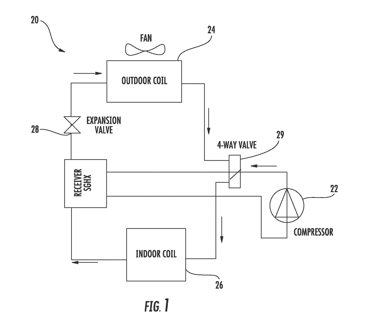
[0034]Referring now to FIG. 1, a vapor compression refrigerant cycle 20 of an air conditioning or refrigeration system is schematically illustrated. Exemplary air conditioning or refrigeration systems include, but are not limited to, split, packaged, chiller, rooftop, supermarket, and transport refrigeration systems for example. A refrigerant R is configured to circulate through the vapor compression cycle 20 such that the refrigerant R absorbs heat when evaporated at a low temperature and pressure and releases heat when condensed at a higher temperature and pressure.

[0035]Within this cycle 20, the refrigerant R flows in a counterclockwise direction as indicated by the arrow. The compressor 22 receives refrigerant vapor from the evaporator 24 and compresses it to a higher temperature and pressure, with the relatively hot vapor then passing to the condenser 26 where it is cooled and condensed to a liquid state by a heat exchange relationship with a cooling medium (not shown) such as ...


PUM


Abstract

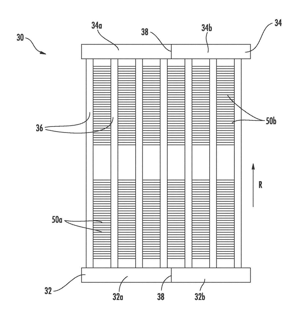
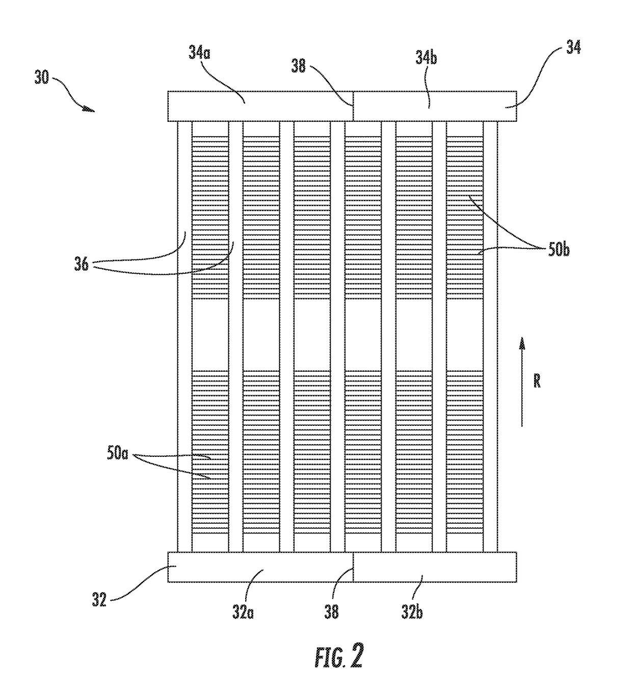
A heat exchanger is provided including a first manifold and a second manifold separated from one another. A plurality of tube segments arranged in a spaced parallel relationship fluidly couple the first and second manifold. The plurality of tube segments includes a bend defining a first slab and a second slab. The second slab is arranged at an angle to the first slab. The heat exchanger has a multi-pass configuration relative to an air flow including at least a first pass and a second pass. The first pass has a first flow orientation and the second pass has a second flow orientation. The second flow orientation is different from the first flow orientation.

Description

BACKGROUND[0001]This invention relates generally to heat pump and refrigeration applications and, more particularly, to a microchannel heat exchanger configured for use in a heat pump or refrigeration system.[0002]Heating, ventilation, air conditioning and refrigeration (HVAC&R) systems include heat exchangers to reject or accept heat between the refrigerant circulating within the system and surroundings. One type of heat exchanger that has become increasingly popular due to its compactness, lower weight, structural rigidity, and superior performance, is a microchannel or minichannel heat exchanger. As compared to conventional plate-and-fin heat exchangers, microchannel heat exchangers are also more environmentally friendly as they utilize less refrigerant charge which typically are synthetic fluids with high GWP (global warming potential). A microchannel heat exchanger includes two or more containment forms, such as tubes, through which a cooling or heating fluid (i.e. refrigerant ...

Claims


Application Information

Patent Timeline
Patent Type & Authority Applications(United States)
IPC IPC(8): F28D1/047F25B13/00F25B47/00F28F1/02F28F9/02F28F19/00
CPCF28D1/0476F25B13/00F25B47/006F28F1/025F28F9/0273F28F19/006F28F1/022F28F9/027F25B39/02F28D1/0471F28F9/22
Inventor JOARDAR, ARINDOM
Owner CARRIER CORP
Learn More