Flow rate measurement device

a flow rate measurement and flow rate technology, applied in the direction of liquid/fluent solid measurement, instruments, other domestic objects, etc., can solve the problems of hindering accurate flow rate measurement, reducing the accuracy of propagation time measurement, etc., to reduce the attenuation of ultrasound, increase the receiving sensitivity, and improve the effect of accuracy

Active Publication Date: 2017-11-30
PANASONIC INTELLECTUAL PROPERTY MANAGEMENT CO LTD
View PDF9 Cites 6 Cited by
  • Summary
  • Abstract
  • Description
  • Claims
  • Application Information

AI Technical Summary

Benefits of technology

[0013]The present invention is to solve the above conventional problem and uses, in place of the ultrasonic transmission film, a turbulence reduction component having opening portions. It is an object to thereby reduce attenuation of ultrasound, increase the receiving sensitivity, and achieve accurate flow rate measurement.
[001

Problems solved by technology

When the receiving sensitivity is too low, the receiving waveform cannot be acquired accurately, which causes

Method used


Image

  • Flow rate measurement device
  • Flow rate measurement device
  • Flow rate measurement device

Examples


embodiment 1

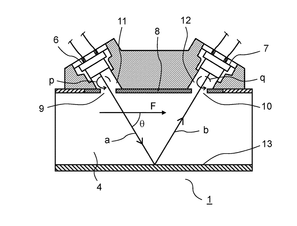
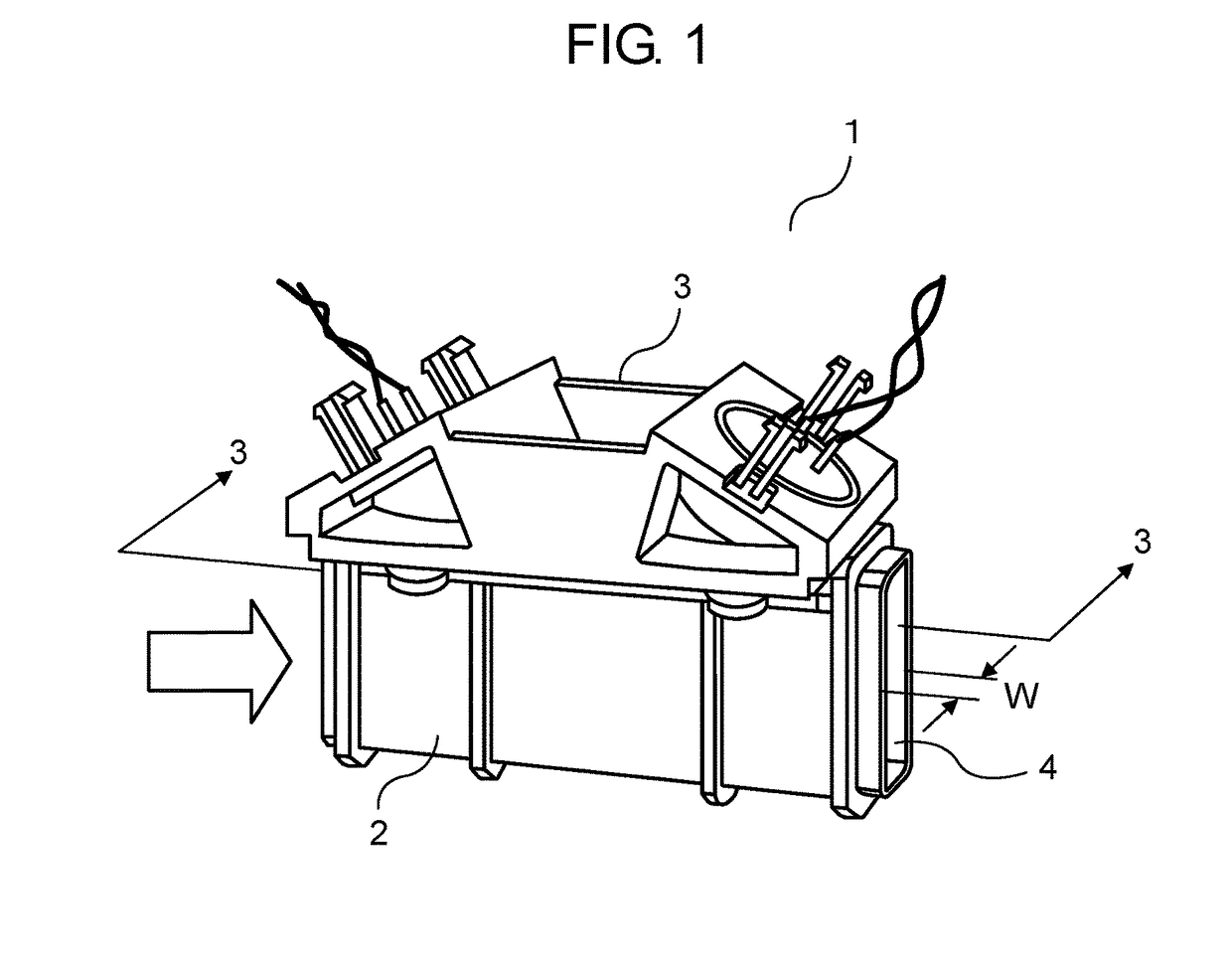
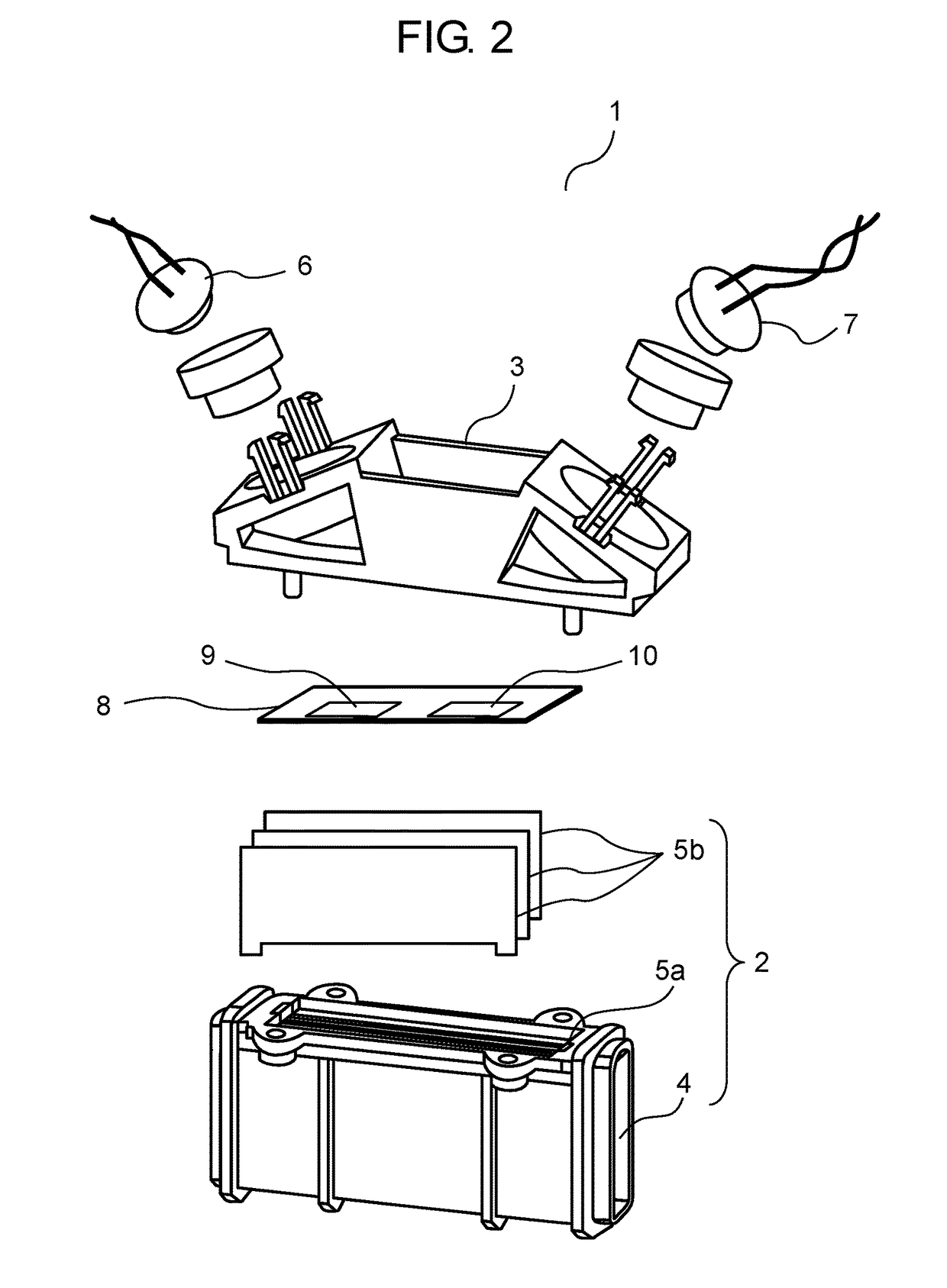
[0026]Embodiment 1 will be described with reference to FIG. 1 to FIG. 5. FIG. 1 is a perspective view of a flow rate measurement device according to Embodiment 1 of the present invention. FIG. 2 is an exploded perspective view of the same flow rate measurement device. FIG. 3 is a cross section of the same flow rate measurement device along line 3-3 in FIG. 1.

[0027]In FIG. 1, flow rate measurement device 1 includes channel block 2 and ultrasonic transceiver block 3.

[0028]In FIG. 2, measurement channel 4 having a rectangular section is formed inside channel block 2. Measurement channel 4 is divided into a plurality of channel layers by a plurality of partition plates 5b. Each partition plate 5b is fixed to channel block 2 by having edges inserted into a plurality of grooves 5a provided in channel block 2.

[0029]First ultrasonic transceiver 6 and second ultrasonic transceiver 7 are attached to ultrasonic transceiver block 3. Both ultrasonic transceivers 6 and 7 have both a function of t...


PUM


Abstract

A flow rate measurement device includes a turbulence reduction component having opening portions and disposed between a measurement channel and a pair of hole portions across which a pair of ultrasonic transceivers are disposed from the measurement channel. The pair of opening portions of the turbulence reduction component each have frame pieces which are substantially identical in width. This makes it possible to reduce, with small attenuation of ultrasound, the occurrence of turbulence that is attributable to entrained flows in the pair of hole portions and is a cause of measurement error, thereby ensuring measurement accuracy.

Description

TECHNICAL FIELD[0001]The present invention relates to a flow rate measurement device which measures a flow rate using ultrasound, and relates in particular to a flow rate measurement device having hole portions between ultrasonic transceivers and a measurement channel.BACKGROUND ART[0002]As the flow rate measurement device of this type, a flow rate measurement device having an ultrasonic transmission film disposed between ultrasonic transceivers and a measurement channel is conventionally known (see Patent Literature 1, for example).[0003]FIG. 6 is an exploded perspective view of a flow rate measurement device disclosed in Patent Literature 1.[0004]As illustrated in FIG. 6, flow rate measurement device 101 includes channel body 102 and sensor block 103.[0005]Channel body 102 includes measurement channel 104 having a rectangular cross section. Measurement channel 104 is divided into a plurality of flat channels by a plurality of partition plates 105.[0006]First ultrasonic transceiver...

Claims


Application Information

Patent Timeline
IPC IPC(8): G01F1/66B32B3/12F15B1/02
CPCG01F1/662B32B3/12F15B1/02B32B2260/023B32B2260/046B32B2262/101B32B2262/106B32B2262/0261B32B2262/0276B32B2262/10B32B5/022B32B5/26B32B2457/08
Inventor NAKAI, HIROSHIYASUDA, KENJISATOU, MASATOMORIHANA, HIDEAKIFUJII, YUJI
Owner PANASONIC INTELLECTUAL PROPERTY MANAGEMENT CO LTD
Why Eureka
Try Eureka