Mirror Display

Active Publication Date: 2017-11-30
LG DISPLAY CO LTD
View PDF2 Cites 17 Cited by
  • Summary
  • Abstract
  • Description
  • Claims
  • Application Information

AI Technical Summary

Benefits of technology

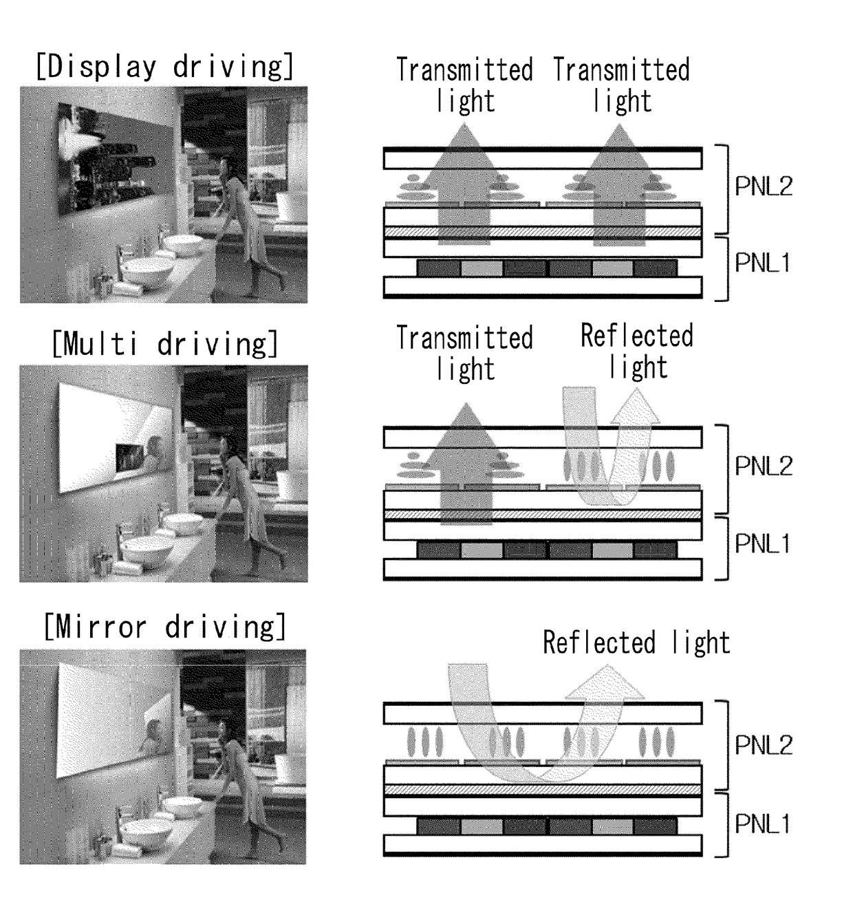
[0007]The embodiments herein describe a mirror display capable of varying a mirror region and a display region, reducing opt

Problems solved by technology

However, since pixels and touch sensors must be time-divisionally driven, the driving method is limited.
Therefore, the in-cell touch driv

Method used


Image

  • Mirror Display
  • Mirror Display
  • Mirror Display

Examples


Embodiment Construction

[0029]Reference will now be made in example embodiments of the invention, of which are illustrated in the accompanying drawings. Wherever possible, the same reference numbers will be used throughout the drawings to refer to the same or like parts. It will be paid attention that detailed description of known arts will be omitted.

[0030]A display panel of a mirror display may be implemented based on a flat panel display device such as a liquid crystal display (LCD), and an organic light emitting display (OLED). In the following embodiments, the liquid crystal display will be mainly described, but the invention is not limited thereto. For example, the display panel described in the following embodiments is exemplified as a display panel of the liquid crystal display device, but may be replaced with a display panel of another flat panel display device such as the OLED display device.

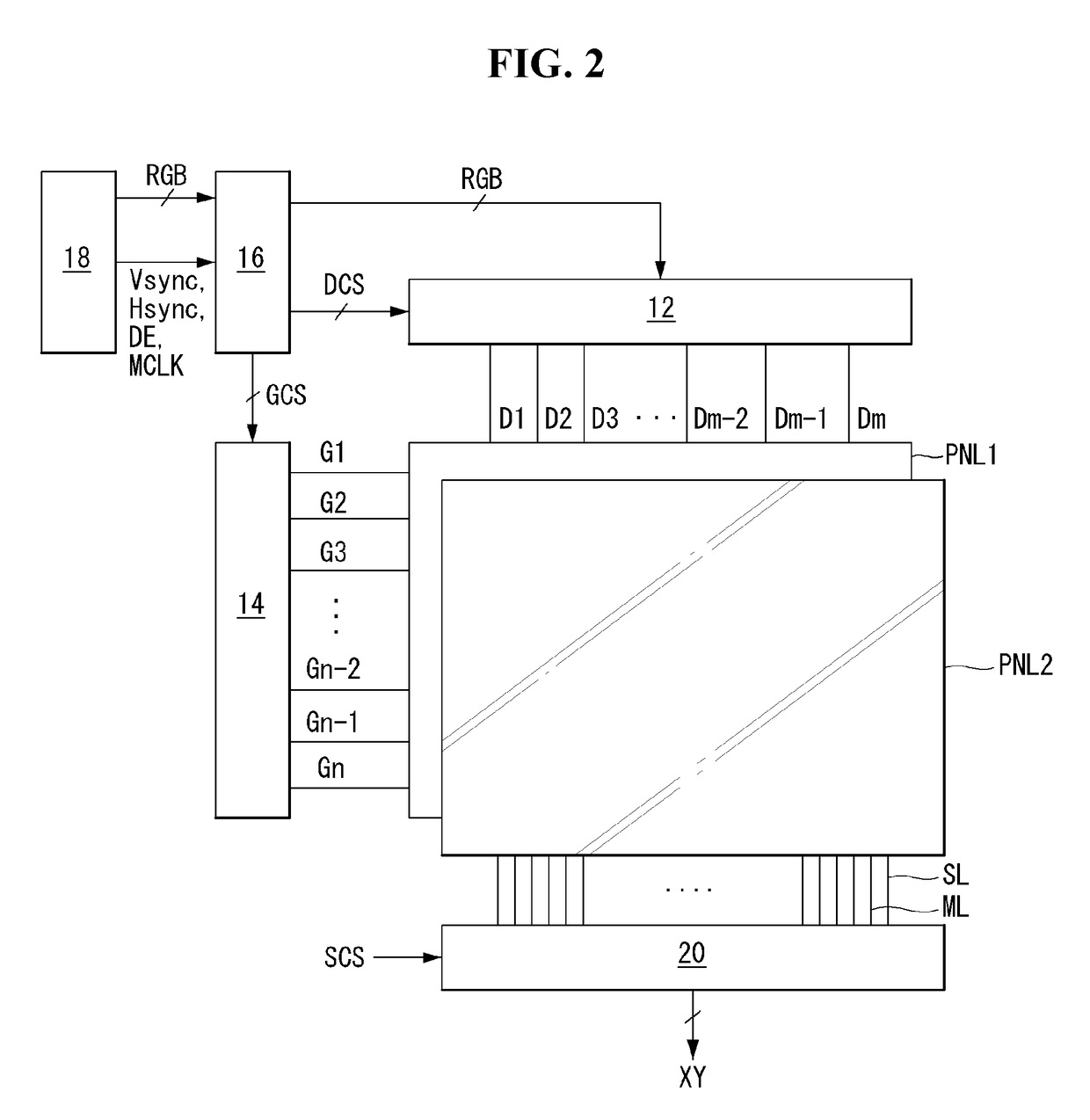
[0031]An in-cell touch sensor can be implemented as a capacitive type touch sensor, for example, a mutual ...


PUM


Abstract

A mirror display is described. The mirror display includes a plurality of first electrodes disposed on a first substrate, a plurality of sensor lines disposed on the first substrate, the plurality of sensor lines connected to the plurality of first electrodes, a plurality of second electrodes disposed on a second substrate, the plurality of second electrodes facing the first substrate, a liquid crystal layer interposed between the plurality of first electrodes and the plurality of second electrodes, a plurality of mirror driving lines on the second substrate, the plurality of mirror driving lines connected to the plurality of second electrodes, and a reflective polarizing film attached to the second substrate.

Description

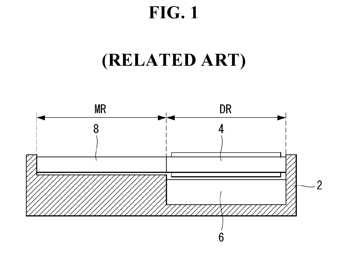
CROSS-REFERENCE TO RELATED APPLICATIONS[0001]This application claims the priority benefit of Korean Patent Application No. 10-2016-0066431 filed on May 30, 2016, which is incorporated by reference in its entirety.BACKGROUNDField of Technology[0002]The present disclosure relates to a mirror display which is driven in a display mode and a mirror mode and is capable of sensing a touch input.Discussion of the Related Art[0003]Recently, display devices for various purposes have been developed. A mirror display has a mirror coupled to a display. Mirror displays are expanding applications such as room mirrors in automobiles and mirrors in clothing stores.[0004]An example of a mirror display is implemented by a method of assembling a reflector 8 and a display 4, 6 in a set frame 2 as shown in FIG. 1. The display may be implemented by a liquid crystal display (LCD) including a display panel 4 and a backlight unit (BLU) 6. The reflector 8 is a mirror region for reflecting light. This mirror d...

Claims


Application Information

Patent Timeline
IPC IPC(8): G06F3/041G02F1/1343G02F1/1362G09G3/36G02F1/1333G02F1/1335G06F3/044
CPCG06F3/0412G02F1/133536G02F1/134309G02F1/13338G09G2300/0426G06F3/044G02F1/136286G02F2203/66G02F2203/02G09G3/3614G02F1/13471G06F3/04166G06F3/0443G02F1/133567G06F3/0416G06F3/0445
Inventor NAM, SANGJINKIM, KYUJINYOO, SEUNGJIN
Owner LG DISPLAY CO LTD
Why Eureka
Try Eureka