
Robust Head Pose Estimation with a Depth Camera

a depth camera and head pose technology, applied in the field of depth camera and head pose estimation, can solve the problems of not being suitable for consumer applications, not being suitable for motion capture, and being difficult to us

Active Publication Date: 2017-11-30
META PLATFORMS INC
View PDF3 Cites 35 Cited by
  • Summary
  • Abstract
  • Description
  • Claims
  • Application Information

AI Technical Summary

Benefits of technology

The patent describes certain functions that make it easier to track and recover from failures, save data from a user's first visit, and recognize and track returning users.

Problems solved by technology

Robust head pose estimation remains a challenging problem.
(1) Methods that use special markers on a user's face to generate head pose information. These methods, while used extensively in motion capture, are not suitable for consumer applications. They often require the use of multiple cameras, carefully calibrated in a studio environment, and the videos are usually processed offline, not real time.
(2) Methods that use facial feature tracking to obtain the head pose information. These methods typically don't work for a wide range of head poses as some or most facial features disappear when the head turns away from the camera. They are also not very accurate as facial features often change with facial expressions and may be affected by lighting conditions. They also don't work well when there is more than one face presence or a face is partially occluded. Some methods require the use of a second camera to overcome these limitations.
(3) Methods that require training or prior training data: These methods can achieve a higher level of accuracy but they often require a large set of training data captured from many subjects in difference head poses. Some methods also require a user to go through a training session first.
(4) Those that use GPU to achieve real time performance: To achieve real time performance, some methods require the use of a specialized graphic processor (GPU).
Use of the technology to generate 3D head models for consumer applications such as sharing, printing and social networking has been hindered by relatively cumbersome approaches to capturing head pose data.

Method used


Image

  • Robust Head Pose Estimation with a Depth Camera
  • Robust Head Pose Estimation with a Depth Camera
  • Robust Head Pose Estimation with a Depth Camera

Examples


Embodiment Construction

[0034]The invention now will be described more fully hereinafter with reference to the accompanying drawings, which form a part hereof, and which show, by way of illustration, specific exemplary embodiments by which the invention may be practiced. This invention may, however, be embodied in many different forms and should not be construed as limited to the embodiments set forth herein; rather, these embodiments are provided so that this disclosure will be thorough and complete, and will fully convey the scope of the invention to those skilled in the art. Among other things, the invention may be embodied as methods, processes, systems, business methods or devices. Accordingly, the present invention may take the form of an entirely hardware embodiment, an entirely software embodiment or an embodiment combining software and hardware aspects. The following detailed description is, therefore, not to be taken in a limiting sense.

[0035]As used herein the following terms have the meanings g...


PUM


Abstract

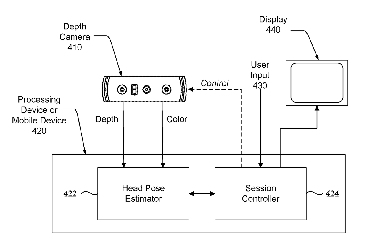
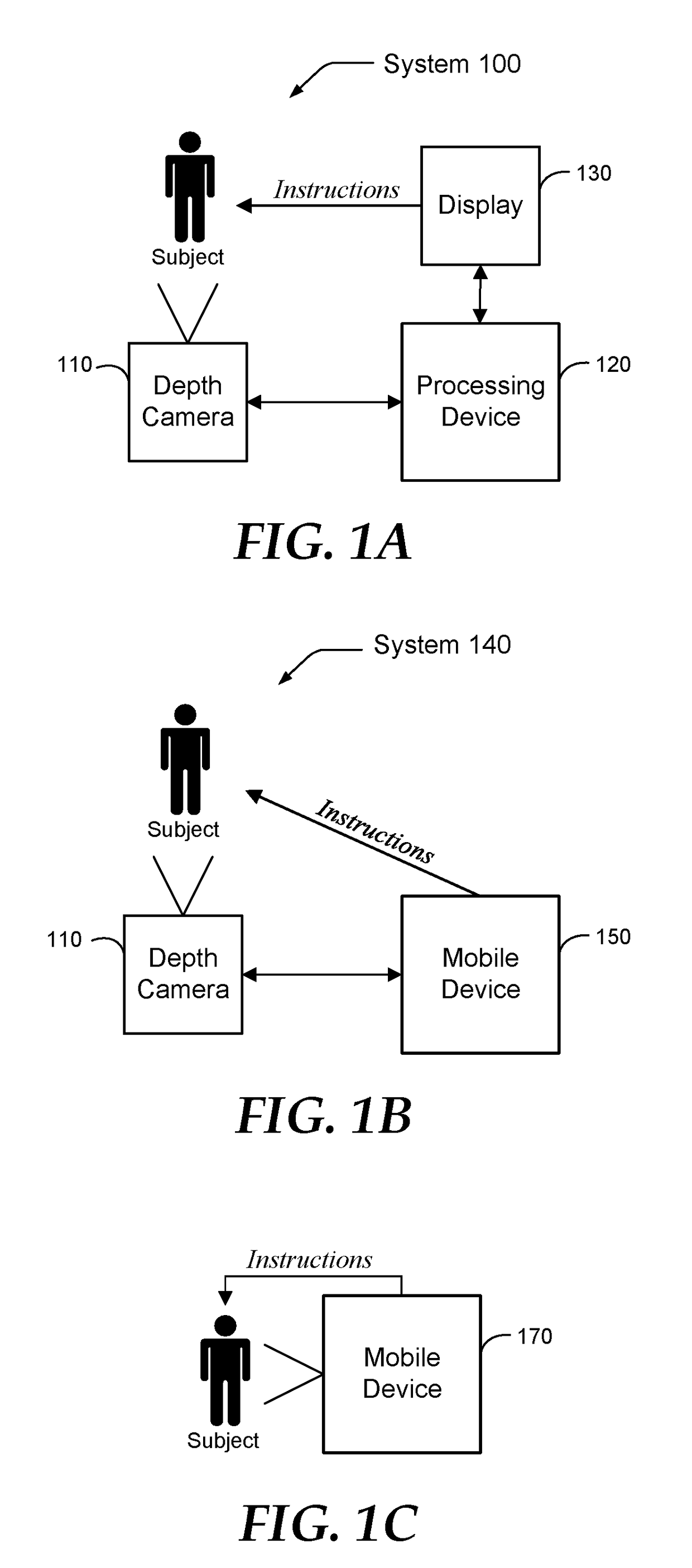
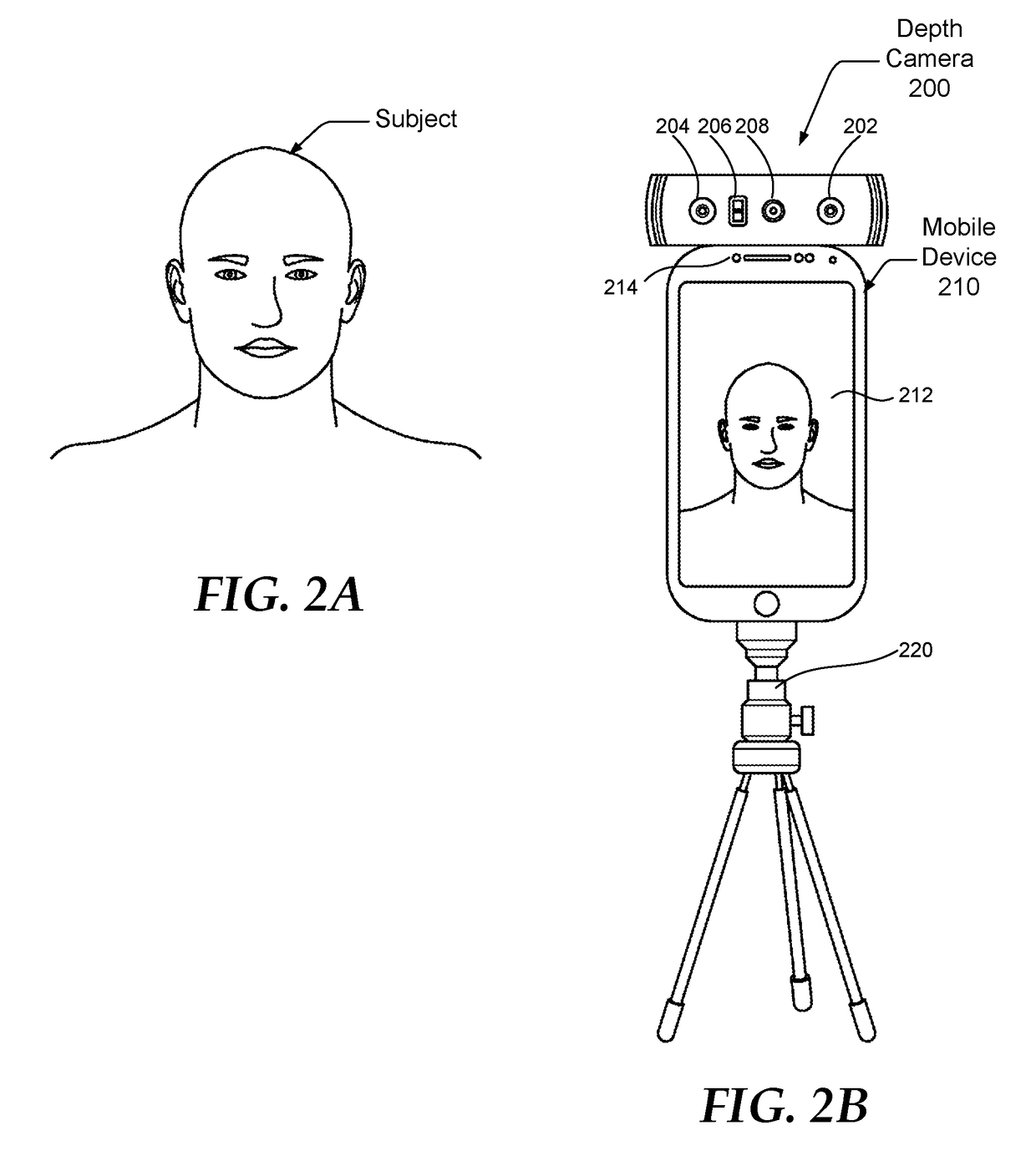
Systems and methods are provided for estimating head pose data from a sequence of depth images of a human subject, and processing the data to generate a continuous estimate of the head pose in a 3-dimensional (3D) space, and to generate a 3D head model for display and further use. The subject is provided instructions to rotate their head in a first direction until a threshold angle of rotation is reached and then are provided instructions to rotate their head in a second direction. The depth camera provides a sequence of captured images which are processed to extract head meshes. After capture is complete the head meshes are merged to generate a 3D model of the subject's head.

Description

BACKGROUND[0001]Human head pose estimation, or head pose estimation as it is commonly referred to, refers to the extraction of 3-dimensional (3D) information that estimates the location and orientation of a person's head using a sequence of digital images of the head taken from a number of angles. Head pose estimation is a step in several computer vision systems. Also, head pose estimation can provide a natural user interface in many computer applications. By knowing the head orientation and position, a computer application can display information responding to the gaze direction of a human operator. One example is a virtual reality application that can generate a view of the virtual world by tracking the viewpoint of a user. Another example is to use the head pose as input for user interactions, such as selecting text or scrolling a document, which allows physically impaired users to control the computer without using a mouse or a keyboard.[0002]The recent introduction of low cost,...

Claims


Application Information

Patent Timeline
IPC IPC(8): G06T7/73G06K9/00G06T17/20G06V10/56
CPCG06T7/74G06T17/20G06T2207/10016G06T2207/10028G06K9/00228G06T2207/30201G06T7/75G06T2207/10021G06T2207/10024G06T2207/20221G06T7/521G06T7/55G06T7/251G06V20/653G06V40/161G06V10/56G06V2201/12H04N23/64H04N23/611H04N23/63H04N13/243
Inventor CHEN, SHENCHANG ERIC
Owner META PLATFORMS INC
Learn More