Wireless communication device and wireless communication method
a wireless communication and wireless communication technology, applied in the direction of wireless communication, electrical equipment, etc., can solve the problems of inability to avoid collision in some cases, adverse influence of deterioration of the throughput of the entire communication system, and inability to transmit excessively, so as to reduce the inequality of transmission opportunities
- Summary
- Abstract
- Description
- Claims
- Application Information
AI Technical Summary
Benefits of technology
Problems solved by technology
Method used
Image
Examples
first embodiment
2. FIRST EMBODIMENT
2-1. Overview of Communication System
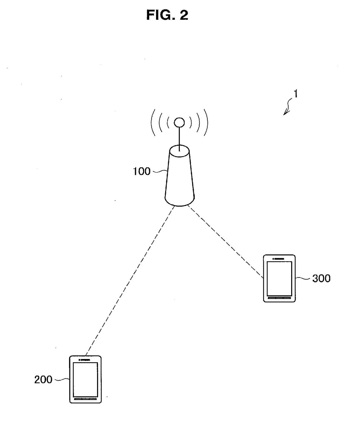
[0064]FIG. 2 is an explanatory diagram showing an overview of a communication system 1 according to an embodiment. As shown in FIG. 2, the communication system 1 includes a base station 100, a wireless terminal 200, and a wireless terminal 300. The communication system 1 is, for example, a system that conforms with a wireless local area network (LAN) or a communication scheme equivalent to the wireless LAN.
[0065]The base station 100 is a wireless communication device that corresponds to a master station which is a center of the communication system 1. The base station 100 may be connected to an external network such as the Internet in a wired or wireless manner. For example, the base station 100 may be an access point in a wireless LAN system.
[0066]The wireless terminals 200 and 300 are wireless communication devices that correspond to slave stations which are each wirelessly connected to the base station 100 to perform communi...
second embodiment
3. SECOND EMBODIMENT
[0167]The embodiment is a mode in which the HE terminal 200 can autonomously perform an operation in the DSC mode without being controlled by the base station 100. The configuration of each device included in the communication system 1 according to the embodiment is the same as that described in the first embodiment. Hereinafter, a characteristic configuration of the HE terminal 200 according to the embodiment will be described.
3-1. Example of Configuration of HE Terminal
(1) Storage Unit 220
[0168]The storage unit 220 according to the embodiment stores the DSC threshold and the DSC transmission parameter in addition to the default threshold and the default transmission parameter. The DSC transmission parameter may be stored in advance or may be stored or updated based on a signal from the base station 100. Examples of the signal from the base station 100 include a beacon and a probe response.
(2) Acquisition Unit 231
[0169]The acquisition unit 231 according to the e...
third embodiment
4. THIRD EMBODIMENT
[0179]The embodiment is a mode in which the HE terminal 200 performs DSC for each channel. First, an overview of the communication system 1 according to the embodiment will be described with reference to FIG. 10.
[0180]FIG. 10 is an explanatory diagram showing an example of a channel according to the embodiment. In the example shown in FIG. 10, the communication system 1 transmits and receives data using four channels, channels A, B, C, and D. A unit channel is set to, for example, 20 MHz. The channels are referred to as the channels A, B, C, and D in order from the unit channel with the lowest frequency. For example, the HE terminal 200 is assumed to transmit data using the channel A when the HE terminal 200 transmits the data with the unit channel using the channel A as a first channel (primary channel). The HE terminal 200 can also transmit data in a bundle of a plurality of channels. The HE terminal 200 according to the embodiment can sort out use or non-use of...
PUM
 Abstract
Description
Claims
Application Information
 - R&D
- Intellectual Property
- Life Sciences
- Materials
- Tech Scout
- Unparalleled Data Quality
- Higher Quality Content
- 60% Fewer Hallucinations
Browse by: Latest US Patents, China's latest patents, Technical Efficacy Thesaurus, Application Domain, Technology Topic, Popular Technical Reports.
© 2025 PatSnap. All rights reserved.Legal|Privacy policy|Modern Slavery Act Transparency Statement|Sitemap|About US| Contact US: help@patsnap.com


