
Printing apparatus

a printing apparatus and printing medium technology, applied in the direction of printing, other printing apparatus, etc., can solve the problems of difficult high-precision printing, easy irregular shape of the wound medium, easy distortion of the character and/or graphic printed on the medium,

Active Publication Date: 2017-12-07
SEIKO EPSON CORP
View PDF2 Cites 3 Cited by
  • Summary
  • Abstract
  • Description
  • Claims
  • Application Information

AI Technical Summary

Benefits of technology

This patent describes a way to prevent defects in a medium when it is being wound onto a roll body. By adjusting the tension in the medium, the influence of changes in front tension can be offset by adjusting the back tension, which keeps the movement of the medium constant. This also reduces the likelihood of winding displacement near the outer edge of the roll body. The technical effect is a more stable and accurate winding process that reduces defects in the medium.

Problems solved by technology

However, when the medium is wound with the constant tension simply applied to the medium, a problem arises in which a wound shape of the medium easily becomes irregular due to a meandering movement of the medium.
Further, another problem arises in which, when the medium is wound while the tension applied to the medium is changed in order to inhibit the irregularity of the wound shape of the medium, characters and / or graphics printed on the medium are easily distorted, thus making it difficult to perform high-precision printing.
With the medium wound into the roll shape by the winding unit (hereinafter referred to as a roll body) in which a portion on a side closer to the center of the roll body has been loosely wound and a portion on a side further away from the center of the roll body has been tightly wound, when a new medium is wound around the outer peripheral surface of the already loosely wound roll body, the outer peripheral surface of the already loosely wound roll body is prone to deform as a result of yielding to a force applied by the new medium wound around the outer peripheral surface, which results in a defect such as wrinkling.
When a smaller front tension is maintained until the end of the winding of the medium, a portion near the outer peripheral surface of the roll body is loosely wound, causing winding displacement to be prone to occur near the outer peripheral surface of the roll body.

Method used


Image

  • Printing apparatus
  • Printing apparatus
  • Printing apparatus

Examples


Embodiment Construction

[0026]An exemplary embodiment of the invention is described below with reference to the accompanying drawings. The exemplary embodiment illustrates one aspect of the invention, and does not limit the invention in any way. The exemplary embodiment can be modified as desired without departing from the scope of the technical concept of the invention. Further, in each of the drawings below, in order to make each of the layers, members, and the like recognizable in terms of size, each of the layers, members, and the like are illustrated to be different to an actual scale.

Exemplary Embodiment

Overview of Printing Apparatus

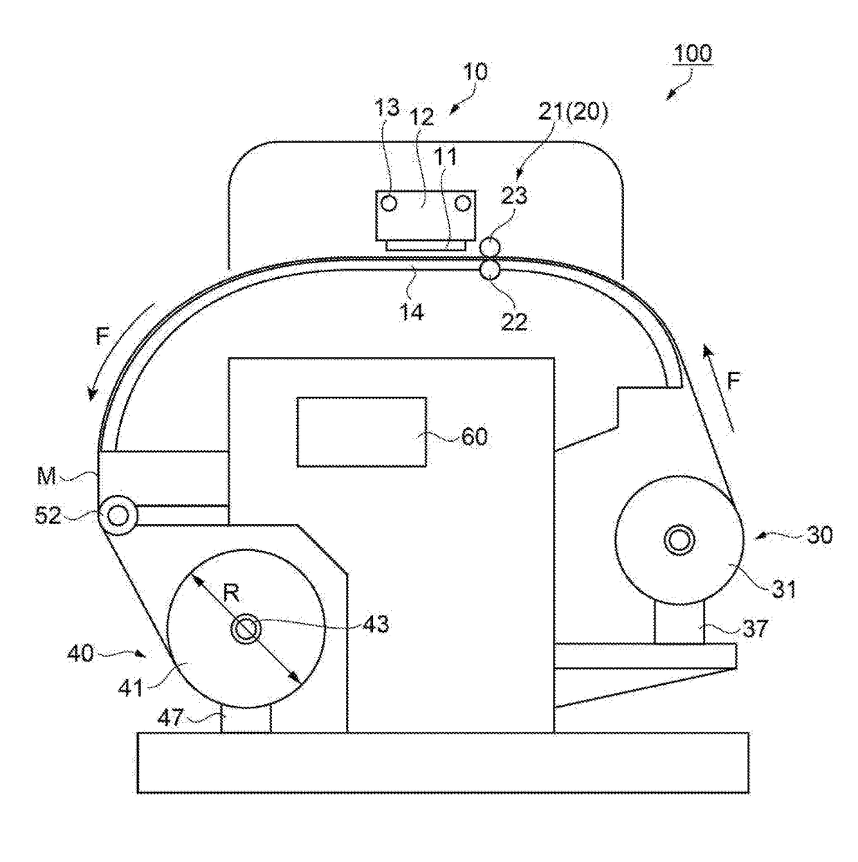
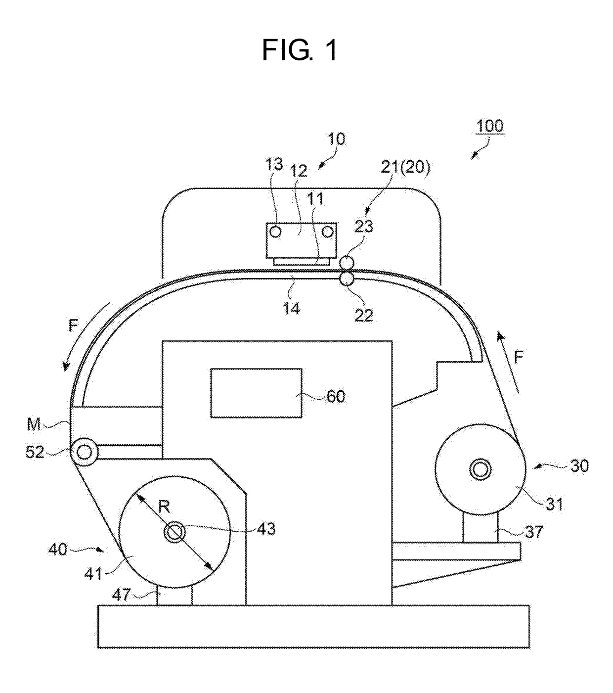
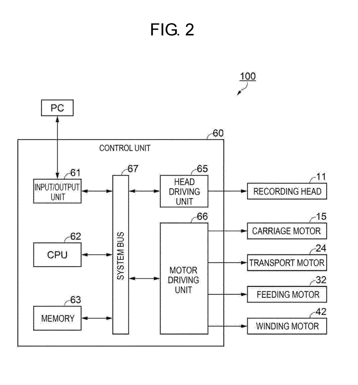
[0027]FIG. 1 is a schematic side view of a printing apparatus according to an exemplary embodiment. FIG. 2 is a control block diagram of the printing apparatus according to the present exemplary embodiment.

[0028]First, with reference to FIG. 1 and FIG. 2, an overview of a printing apparatus 100 according to the exemplary embodiment is described.

[0029]As illustrated in FIG...


PUM


Abstract

A printing apparatus is provided with: a recording head that performs printing on a medium fed out from a transport roller pair; a feeding unit that feeds the medium to the transport roller pair; and a winding unit that winds, into a roll shape, the medium subjected to the printing by the recording head. The winding unit winds the medium while adjusting a front tension acting on the medium between the transport roller pair and the winding unit, depending on a diameter of the medium wound into the roll shape. The feeding unit feeds the medium while adjusting a back tension acting on the medium between the transport roller pair and the feeding unit, depending on changes in the front tension.

Description

BACKGROUND1. Technical Field[0001]The present invention relates to a printing apparatus.2. Related Art[0002]For example, a medium processing apparatus (a printing apparatus) is proposed that transports a medium using a roll-to-roll method and performs processing (printing) on the medium (JP-A-2014-69932, for example).[0003]The printing apparatus disclosed in JP-A-2014-69932 includes: a medium feeding mechanism that feeds a medium wound into a roll shape; a main body unit that performs printing on the medium; a medium winding mechanism that winds, into a roll shape, the medium subjected to the printing; a second tension applying unit that applies a tension to the medium between the medium feeding mechanism and the main body portion; and a first tension applying unit that applies a tension to the medium between the medium winding mechanism and the main body portion. Further, the first tension applying unit and the second tension applying unit control the tension applied to the medium ...

Claims


Application Information

Patent Timeline
IPC IPC(8): B41J15/04
CPCB41J15/046B41J15/16
Inventor NAKATA, TOSHIO
Owner SEIKO EPSON CORP
Learn More