Flexure hinge

Active Publication Date: 2017-12-07
WIPOTEC GMBH
View PDF0 Cites 1 Cited by
  • Summary
  • Abstract
  • Description
  • Claims
  • Application Information

AI Technical Summary

Benefits of technology

[0027]Preferably, the flexure hinge is provided with a plurality of recesses, which lie side by side in width direction Z. This results in a uniform stress distribution over the viewed section width B. Expediently, the recesses have the same shape, which simplifies production and calculation. Moreover, the recesses preferably have the same spacings from each other in the Z d

Problems solved by technology

In any case, besides the desired reduction of the stiffness, the stability (load capacity, strength) is always undesirably reduced, even if it is represented as “acceptable” in the literature.
It is disadvantageous with these known solutions that with a de

Method used


Image

  • Flexure hinge
  • Flexure hinge
  • Flexure hinge

Examples


Embodiment Construction

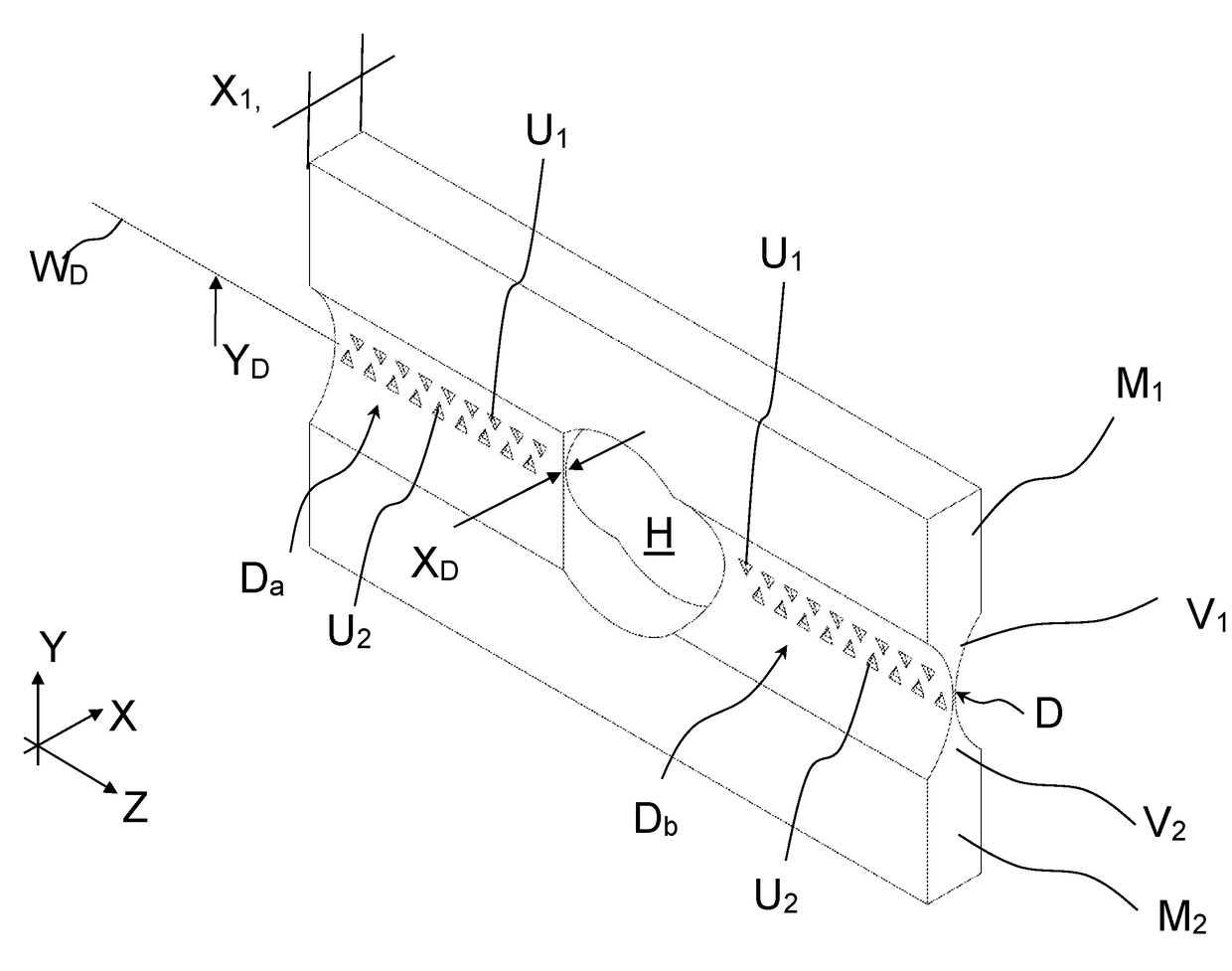
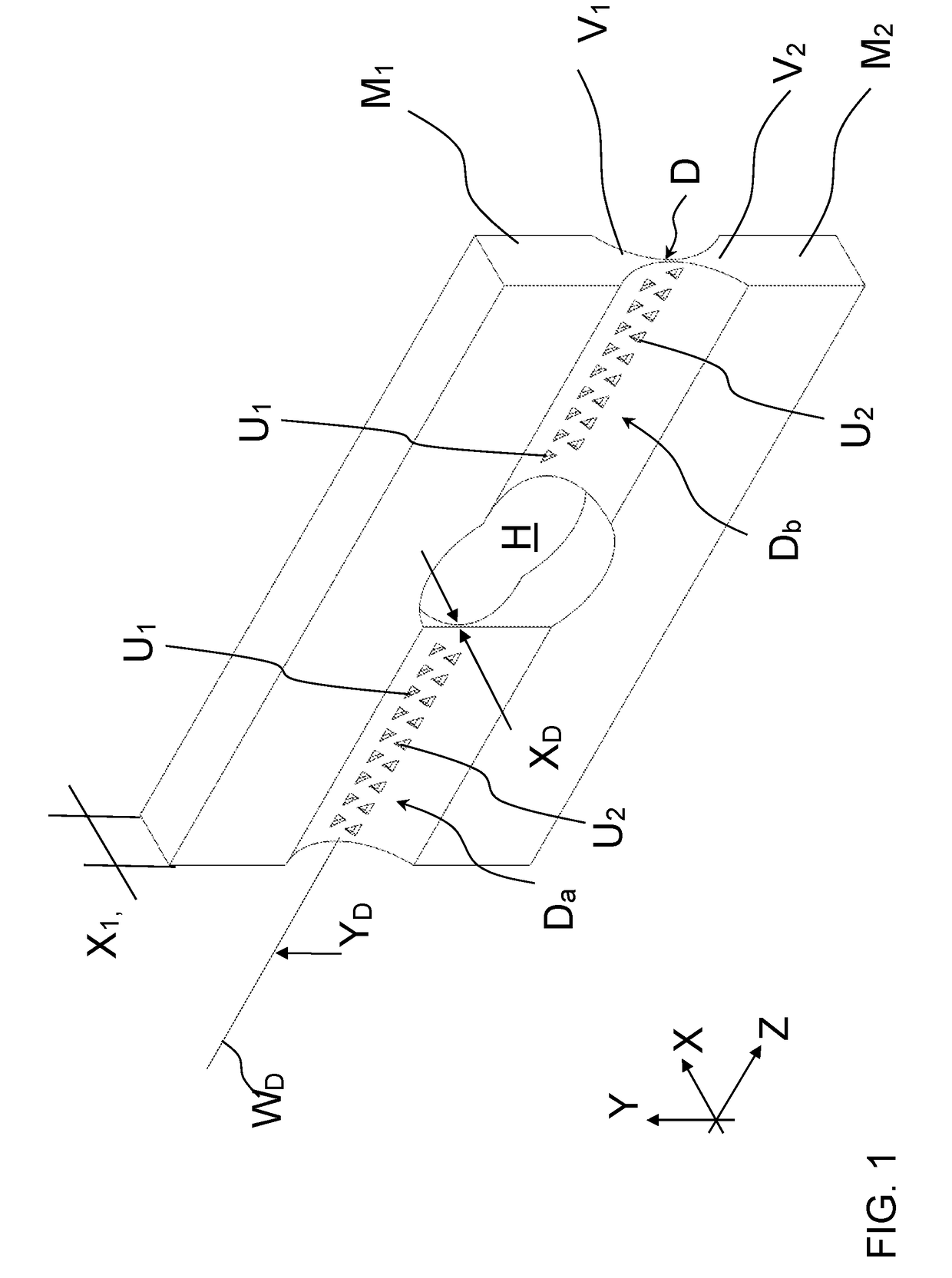
[0043]FIG. 1 shows a flexure hinge according to the invention in a simplified perspective view. The hinge comprises two material segments M1, M2, which are monolithically joined to each other via a thin spot D. The thin spot D is formed by two tapering sections V1, V2, which extend in a lengthwise direction Y toward each other as part of the material segments M1, M2, where the thickness measured perpendicular thereto in the X direction steadily decreases up to a minimal thickness XD, at which the actual thin spot D exists. It extends along a pivot axis WD in a width direction Z, which is perpendicular to the X and Y directions. The first material segment M1 can be pivoted with respect to the second material segment M2 about the thin spot D, where an idealized pivot axis WD runs in the Z direction at the lengthwise position YD of the thin spot D. An opening H made centrally in the thin spot D divides the thin spot into two segments Da and Db in the Z direction.

[0044]A plurality of re...


PUM

PropertyMeasurementUnit
Lengthaaaaaaaaaa
Thicknessaaaaaaaaaa
Electrical resistanceaaaaaaaaaa

Abstract

A flexure hinge with two material segments connected to each other via a material tapering to a thin spot which defines a pivot axis between the two material segments. The material segments are provided with recesses such that the strength existing in the thin spot with respect to normal stresses or bending stresses is kept largely constant within a distance from the thin spot.

Description

TECHNICAL FIELD OF THE INVENTION[0001]The invention concerns a flexure, or thin spot, hinge for movable connection of material segments.BACKGROUND OF THE INVENTION[0002]Hinges are often used in industry to connect components movably to each other. The hinges are intended to allow movements and transfers of force in certain directions, but prevent them in other directions. An example of this is a solid body or flexure hinge. In this case two material segments that are connected to each other monolithically are provided with a material tapering (a so-called “thin spot”) in order to enable movements about a pivot axis formed by the thin spot. Pivoting movements about axes perpendicular thereto and translatory relative movements of the two material segments, however, are prevented.[0003]Such flexure hinges are known in particular from modern weighing technology, which utilizes monolithic link arm mechanisms, so-called monoblocks. Through this, production costs are reduced and the precis...

Claims


Application Information

Patent Timeline
IPC IPC(8): F16C11/12B23K26/06B23K26/384E05D1/02
CPCF16C11/12B23K26/0619B23K26/384E05D1/02G01G21/07G01G21/166G01G21/188G01G21/20G01G21/244
Inventor RUBEL, ANDREASBUR, CHRISTIAN
Owner WIPOTEC GMBH
Why Eureka
Try Eureka