Device and a method for fabricating a part by injection molding

a technology of injection molding and parts, which is applied in the direction of machines/engines, other domestic objects, mechanical equipment, etc., can solve the problems of complex and expensive compensation mold operation, inability to determine the shape of compensation mold, and deformation of extracted parts

Active Publication Date: 2017-12-14
SN DETUDE & DE CONSTR DE MOTEURS DAVIATION S N E C M A
View PDF2 Cites 4 Cited by
  • Summary
  • Abstract
  • Description
  • Claims
  • Application Information

AI Technical Summary

Benefits of technology

[0017]An object of the present invention is to remedy the above-mentioned drawbacks. More precisely, an object of the present invention is to propose a solution that makes it possible to provide a mold that is suitable for compensating the deformation of a part relative to its nominal shape, and to do so without it being necessary to make intermediate molds.
[0022]Advantageously, the presence of deformation elements for modifying the mold cavity makes it possible to prepare only one mold. By modifying the shape of the mold cavity it becomes possible, in particular, to compensate for any deformation in the fabricated part as extracted from the mold. The shape of such a cavity can thus be controlled into an infinity of configurations by said deformation elements. Consequently, costs in terms of time for making or optimizing such a mold are minimized, since applying a new configuration no longer requires a new mold to be made. Thus, once an optimum configuration has been identified for the deformation elements, this configuration can be conserved for producing molds in series, or indeed for using a single mold having its mold cavity deformed in compliance with the identified optimum configuration.

Problems solved by technology

Such defects may be explained in particular by the fact that residual stresses apply to the part during its fabrication in the mold (e.g.: polymerization gradient, winding tension for a part made of composite material), which residual stresses are released when the part is extracted from the mold, thereby leading to deformation of the extracted part.
Nevertheless, making a compensation mold of this type remains an operation that is complex and expensive.
For example, the composite materials used for making mechanical parts present properties that depend on numerous factors (e.g.: three-dimensional weaving, winding tension, injection parameters, and polymerization parameters) that cannot always be completely determined from a theoretical point of view by the manufacturers of such parts.
It is thus often not possible to determine the shape of a compensation mold by calculation.
At present, using such a solution is found not only to be expensive, but also time consuming for producing molded parts.

Method used


Image

  • Device and a method for fabricating a part by injection molding
  • Device and a method for fabricating a part by injection molding
  • Device and a method for fabricating a part by injection molding

Examples


Embodiment Construction

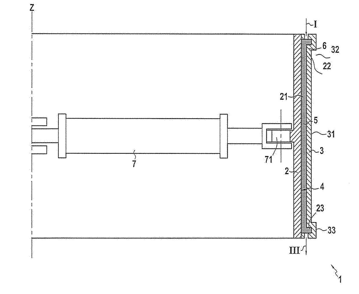
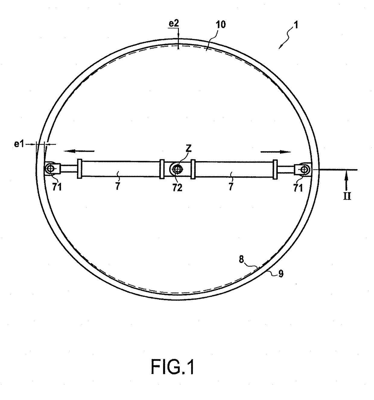
[0047]FIG. 1 shows an injection molding device comprising in particular a mold 1 that is a body of revolution, e.g. of circular or cylindrical shape and presenting a section that is annular.

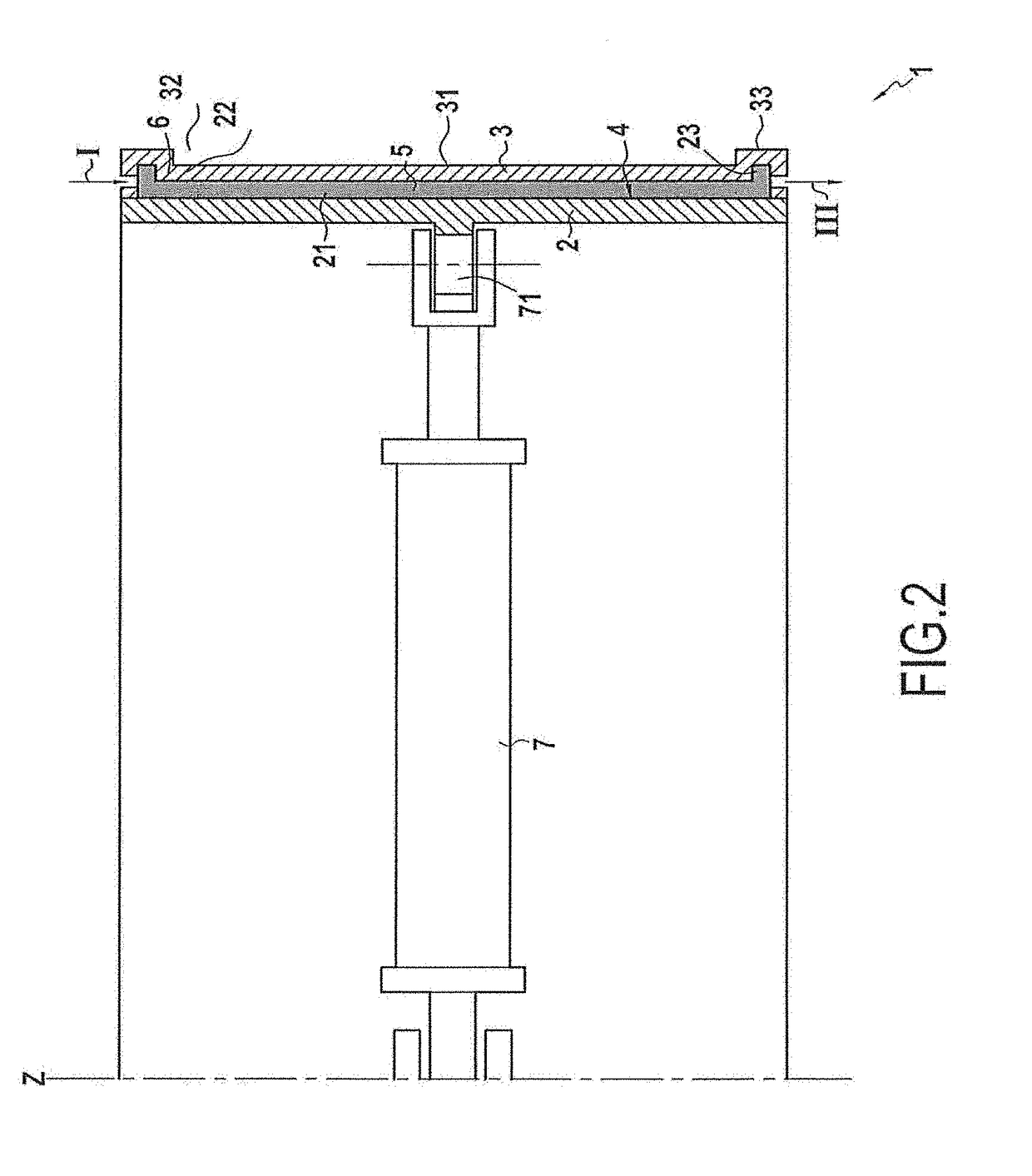
[0048]As can be seen in FIG. 2, which is an axial section on plane II-II of FIG. 1, such a mold 1 is made up of a support 2 and a countermold 3 which between them define a mold cavity 4, which presents a shape that is circular or annular.

[0049]The support 2 is to act as a support for a fiber preform 5 of a part that is to be made. By way of example, the preform 5 is a preform made of carbon fibers with three-dimensional or multilayer weaving between warp yarns and weft yarns.

[0050]In this example, the support 2 has an outer annular surface with the same profile as the part that is to be made, in this example the surface of a fan casing.

[0051]The countermold 3 is placed facing the support 2 of the mold 1 so as to constitute the closed volume of the mold cavity 4. In the example shown, the preform ...


PUM

PropertyMeasurementUnit
shapeaaaaaaaaaa
temperatureaaaaaaaaaa
mechanical strengthaaaaaaaaaa

Abstract

An injection molding device for fabricating a part, the device including an injection mold, the mold being formed of a support and a countermold that are distinct and that define between them a mold cavity presenting a first shape; and at least one injection device for injecting a fluid material into the mold cavity; the device including deformation elements configured to modify the shape of the mold cavity into a second shape distinct from the first shape.

Description

BACKGROUND OF THE INVENTION[0001]The invention relates to the field of fabricating injection molded parts. More precisely, the invention relates to an injection molding device and method for fabricating a part that make it possible to avoid potential deformation of the part relative to its expected nominal shape as can occur during solidification (e.g. polymerization) and as observed on extracting the part from the mold.[0002]Existing injection molding methods include in particular the resin transfer molding (RTM) method in which a mold comprises two half-shells that, when placed one against the other, confine a mold cavity. A fiber preform is inserted into the cavity between the two half-molds and then resin is injected into the cavity. The resin is polymerized while keeping the two half-shells closed. Depending on the desired rate of production, polymerization may be performed at ambient temperature or by heating. Such a method can be used to make parts:[0003]that are bodies of re...

Claims


Application Information

Patent Timeline
Patent Type & Authority Applications(United States)
IPC IPC(8): B29C45/37B29C45/72B29C45/26F01D25/24B29L31/00
CPCB29C45/376B29C45/7207B29C45/2628F05D2300/614B29L2031/7504F05D2230/20F01D25/24B29C70/48B29C33/308B29C45/0025B29L2031/082
Inventor MOST, VINCENT BERNARD SERGE
Owner SN DETUDE & DE CONSTR DE MOTEURS DAVIATION S N E C M A
Why Eureka
Try Eureka