Air conditioning system and method for leakage detection in an air conditioning system

Active Publication Date: 2017-12-14
TRUMA GERAETETECHNIK GMBH & CO
View PDF10 Cites 9 Cited by
  • Summary
  • Abstract
  • Description
  • Claims
  • Application Information

AI Technical Summary

Benefits of technology

[0008]The object is solved by an air conditioning system as mentioned above, which includes a leakage detection system, comprising a room temperature sensor which is formed to detect a room temperature of the room to be air-conditioned upstream of the refrigerant evaporator on an air inlet side, an inlet temperature sensor which is formed to detect a refrigerant temperature at a refrigerant inlet of the refrigerant evaporator, an outlet temperature sensor which is formed to detect a refrigerant temperature at a refrigerant outlet of the refrigerant evaporator, and a calculating unit which is coupled with the room temperature sensor, the inlet temperature sensor and the outlet temperature sensor. The calculating unit is formed to calculate an outlet differential temperature as difference of the room temperature and the refrigerant temperature at the refrigerant outlet and an evaporator differential temperature as difference of the refrigerant temperature at the refrigerant inlet and at the refrigerant outlet. The calculation of these two differential temperatures can be effected in a single calculating unit. Alternatively, each of the differenc

Problems solved by technology

In the case of a leakage the refrigerant ci

Method used


Image

  • Air conditioning system and method for leakage detection in an air conditioning system
  • Air conditioning system and method for leakage detection in an air conditioning system
  • Air conditioning system and method for leakage detection in an air conditioning system

Examples


Embodiment Construction

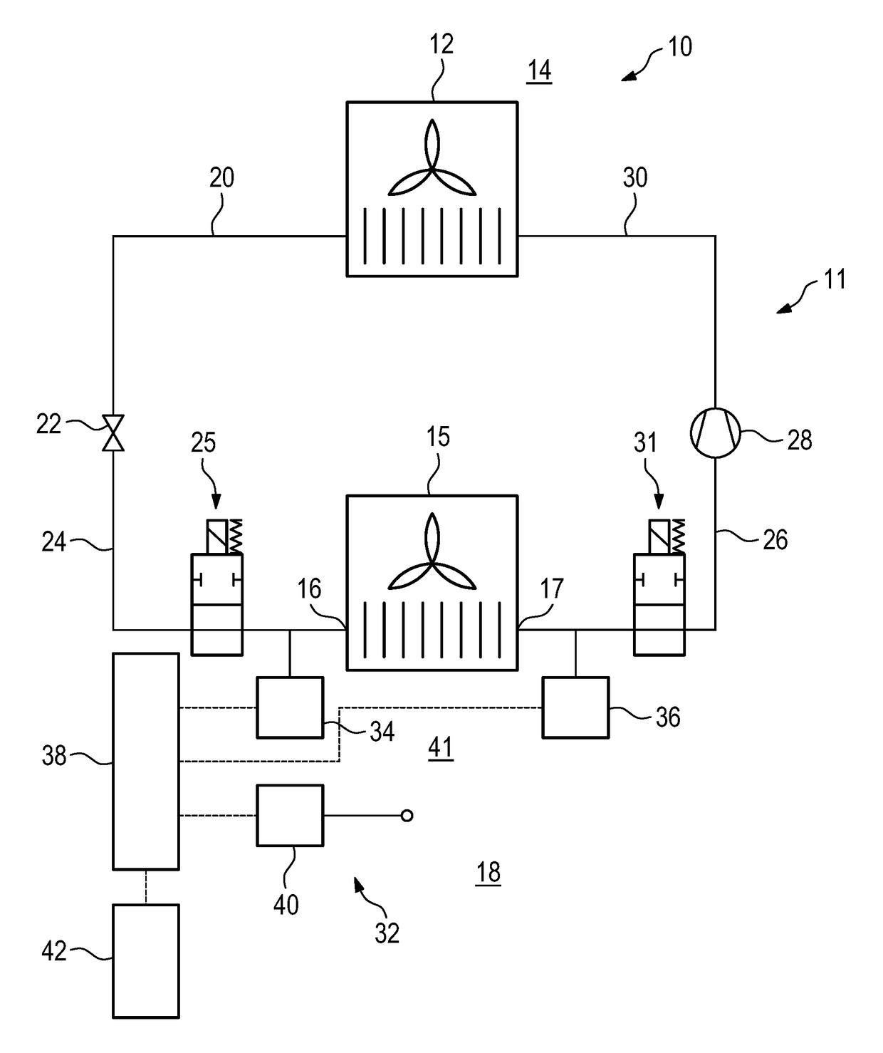
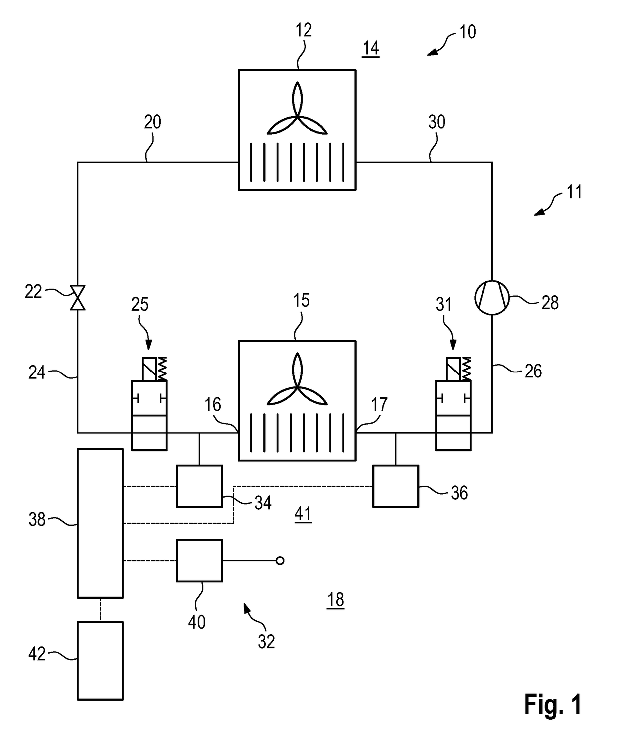
[0033]FIG. 1 shows an overview of an air conditioning system 10. The air conditioning system 10 for example can be arranged in a leisure vehicle.

[0034]The air conditioning system 10 comprises a refrigerant circuit 11 with a refrigerant condenser 12, which is in heat exchange with an environment 14, and a refrigerant evaporator 15 with a refrigerant inlet 16 and a refrigerant outlet 17, which is in heat exchange with a room 18 to be air-conditioned.

[0035]A refrigerant circulates via a refrigerant line 20 from the refrigerant condenser 12 to a refrigerant throttle 22 and from there via a refrigerant line 24 to the refrigerant evaporator 15. The refrigerant line 24 also includes a refrigerant inlet valve 25, by means of which the refrigerant inlet 16 selectively can be separated from the rest of the refrigerant circuit 11.

[0036]Proceeding from the refrigerant evaporator 15, the refrigerant circulates via a refrigerant line 26 to a refrigerant compressor 28, which via a refrigerant line...


PUM


Abstract

There is described an air conditioning system with a refrigerant circuit, wherein the air conditioning system includes a leakage detection system. The leakage detection system comprises a room temperature sensor, an inlet temperature sensor for detection of a refrigerant temperature at a refrigerant inlet of a refrigerant evaporator, and an outlet temperature sensor for detection of a refrigerant temperature at a refrigerant outlet of the refrigerant evaporator. The sensors (34, 36, 40) are coupled with a calculating unit. In addition, there is described a method for leakage detection, in which a room temperature of the room to be air-conditioned is detected before the refrigerant evaporator on an air inlet side, a refrigerant inlet temperature is detected at the refrigerant inlet of a refrigerant evaporator, and a refrigerant outlet temperature is detected at a refrigerant outlet of the refrigerant evaporator.

Description

[0001]The invention relates to an air conditioning system with a refrigerant circuit, wherein as seen in circulation direction of a refrigerant the air conditioning system comprises a refrigerant condenser which can be in heat exchange with an environment, a refrigerant throttle, a refrigerant evaporator which can be in heat exchange with a room to be air-conditioned, and a refrigerant compressor.[0002]Furthermore, the invention relates to a method for leakage detection in an air conditioning system as mentioned above.BACKGROUND OF THE INVENTION[0003]In the prior art, air conditioning systems are used in a wide variety of fields. In the air conditioning systems refrigerants are used, which have properties adapted to the respective purpose. In conventional air conditioning systems the refrigerants contain fluorinated greenhouse gases, in particular fluorinated hydrocarbons.[0004]With a growing environmental awareness and ever stricter legal requirements, for example of the EU order o...

Claims


Application Information

Patent Timeline
IPC IPC(8): B60H1/00B60H1/32
CPCB60H1/00978B60H1/00364B60H2001/3263B60H1/00985B60H2001/3261B60H1/00885F25B49/005F25B2500/19F25B2500/222F25B2700/2104F25B2700/21174F25B2700/21175F25B41/22F25B41/24F25B2400/12
Inventor MATHE, CHRISTIANHUMMEL, GEORGHAERTIG, SEBASTIANHILLER, WERNERGUMPP, DANIELVENSCHOTT, MATHIAS
Owner TRUMA GERAETETECHNIK GMBH & CO
Why Eureka
Try Eureka