Method for Compensating Pattern Placement Errors Caused by Variation of Pattern Exposure Density in a Multi-Beam Writer

Active Publication Date: 2017-12-14
IMS NANOFABTION
View PDF1 Cites 22 Cited by
  • Summary
  • Abstract
  • Description
  • Claims
  • Application Information

AI Technical Summary

Benefits of technology

[0021]Furthermore, for determining the local pattern density evolution it may greatly reduce the amount of calculations while not deteriorating the quality of the compensation achieved too much, if the LPd evolution is determined for a reduced set of points in time, which each represent one of a sequence of subsequent time intervals (assuming the density of these points in time is sufficient to describe the variation of the LPd over time). For instance, time is divided into time intervals which each contain the

Problems solved by technology

Furthermore, where the LPd is changed, it is often possible to describe the variation

Method used


Image

  • Method for Compensating Pattern Placement Errors Caused by Variation of Pattern Exposure Density in a Multi-Beam Writer
  • Method for Compensating Pattern Placement Errors Caused by Variation of Pattern Exposure Density in a Multi-Beam Writer
  • Method for Compensating Pattern Placement Errors Caused by Variation of Pattern Exposure Density in a Multi-Beam Writer

Examples


Embodiment Construction

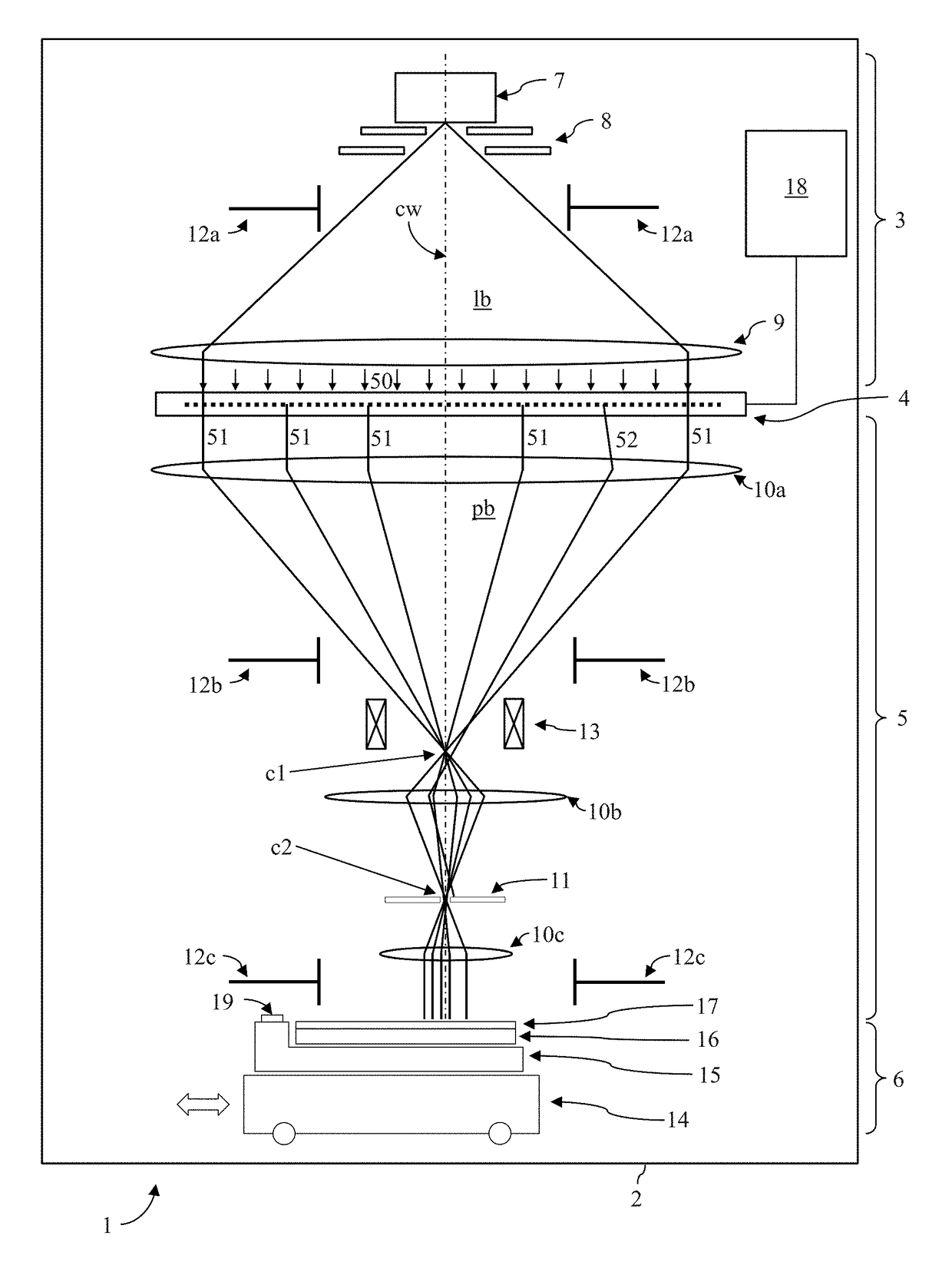
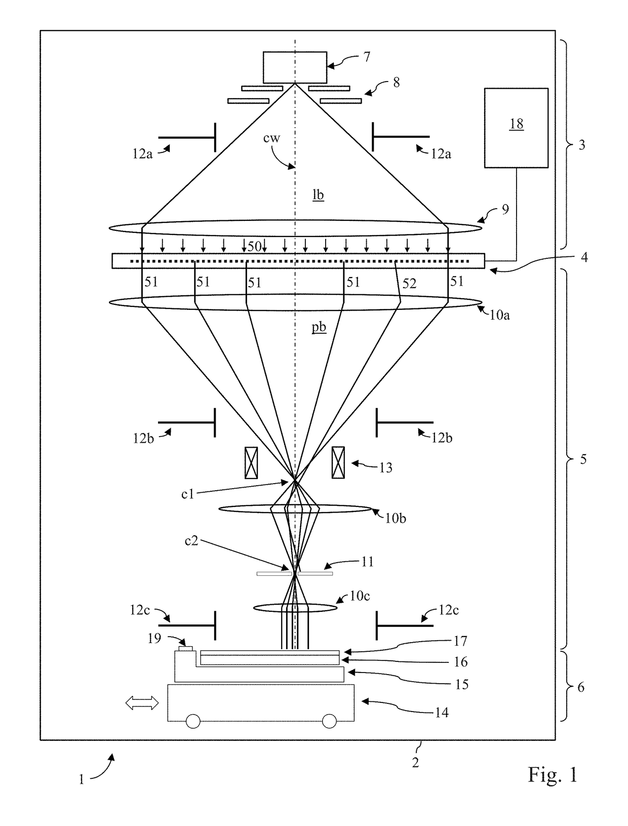
[0061]The detailed discussion of the invention is given hereinafter in the context of several exemplary embodiments. It will be appreciated that the invention is not restricted to the exemplary embodiments discussed in the following, which are given for illustrative purpose and merely present suitable implementations of the invention. Specifically, first a general description of a multi-beam writer (MBW) tool is provided and how a pattern is written therein (FIGS. 1-7); then, with reference to FIGS. 8-12 follows a discussion of the occurrence of pattern placement errors (registration offset) and compensation of these errors as proposed by the invention, based on an example of a pattern with varying local pattern density. Within this disclosure, the terms “displacement” and “placement error” are used interchangeable and without any distinction.

Lithographic Apparatus

[0062]An overview of a lithographic apparatus suitable to employ the preferred embodiment of the invention is shown in F...


PUM


Abstract

A method for compensating pattern placement errors during writing a pattern on a target in a charged-particle multi-beam exposure apparatus including a layout generated by exposing a plurality of beam field frames using a beam of electrically charged particles, wherein each beam field frame has a respective local pattern density, corresponding to exposure doses imparted to the target when exposing the respective beam field frames. During writing the beam field frames, the positions deviate from respective nominal positions because of build-up effects within said exposure apparatus, depending on the local pattern density evolution during writing the beam field frames. To compensate, a displacement behavior model is employed to predict displacements; a local pattern density evolution is determined, displacements of the beam field frames are predicted based on the local pattern density evolution and the displacement behavior model, and the beam field frames are repositioned accordingly based on the predicted values.

Description

CROSS-REFERENCE TO RELATED APPLICATIONS[0001]This application claims priority to U.S. Provisional Patent Application No. 62 / 349,483, filed Jun. 13, 2016, and is hereby incorporated by reference in its entirety.FIELD OF THE INVENTION AND DESCRIPTION OF PRIOR ART[0002]The invention relates to certain improvements in writing a pattern on a target in a charged-particle multi-beam exposure apparatus, and more specifically to a method for compensating pattern placement errors during writing a pattern on a target in a charged-particle multi-beam exposure apparatus, wherein a layout is generated by exposing a plurality of beam field frames using a beam of electrically charged particles, which represent two-dimensional arrangements of pixels on the target and are written in a given time sequence, wherein each beam field frame has a nominal position on the target, and in each beam field frame each pixel has a relative nominal position and an exposure value.[0003]Methods of the above-described...

Claims


Application Information

Patent Timeline
IPC IPC(8): G03F1/36G06F17/50
CPCG03F1/36G06F17/5081G06F17/5072G06F17/5036G03F1/78H01J37/3026H01J37/3177H01J2237/30461H01J2237/31761
Inventor PLATZGUMMER, ELMAR
Owner IMS NANOFABTION
Why Eureka
Try Eureka