Input detection device and electronic device

a detection device and input technology, applied in the field of input detection devices and electronic devices, can solve the problems of increasing manufacturing costs, not being described nor recognized, so as to achieve the effect of increasing manufacturing costs and increasing the size of input devices

Active Publication Date: 2017-12-14
JAPAN DISPLAY INC
View PDF24 Cites 5 Cited by
  • Summary
  • Abstract
  • Description
  • Claims
  • Application Information

AI Technical Summary

Benefits of technology

[0007]Conventionally, in a case in which both a finger and a pen are desired to be detected, it is necessary to use a capacitive sensing touch panel and an electromagnetic induction touch panel in such a manner that one of them is overlapped with the other. As a result, this causes an increase in size of an input device, thereby also increasing manufacturing costs. In addition, it is necessary to additionally mount a display device on the touch panel in an overlapping manner in order to display an image on the touch panel.

Problems solved by technology

As a result, this causes an increase in size of an input device, thereby also increasing manufacturing costs.
However, a capacitive sensing touch panel is neither described nor recognized in Patent Document 1.

Method used


Image

  • Input detection device and electronic device
  • Input detection device and electronic device
  • Input detection device and electronic device

Examples


first embodiment

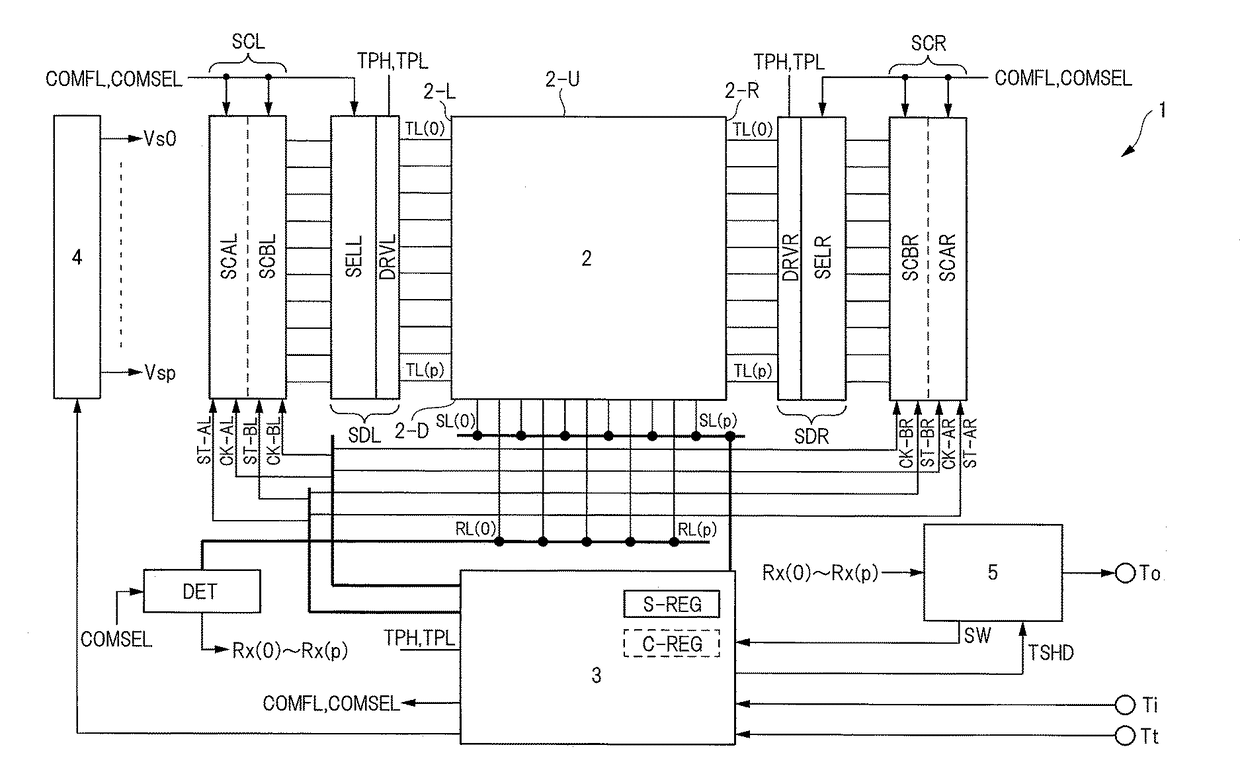
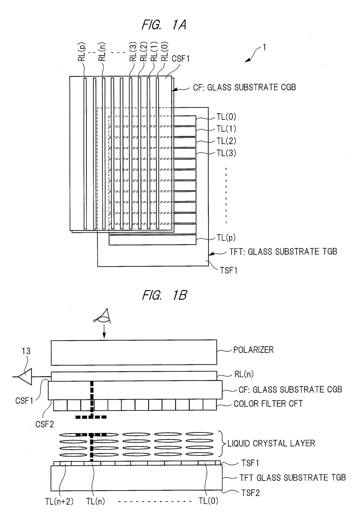
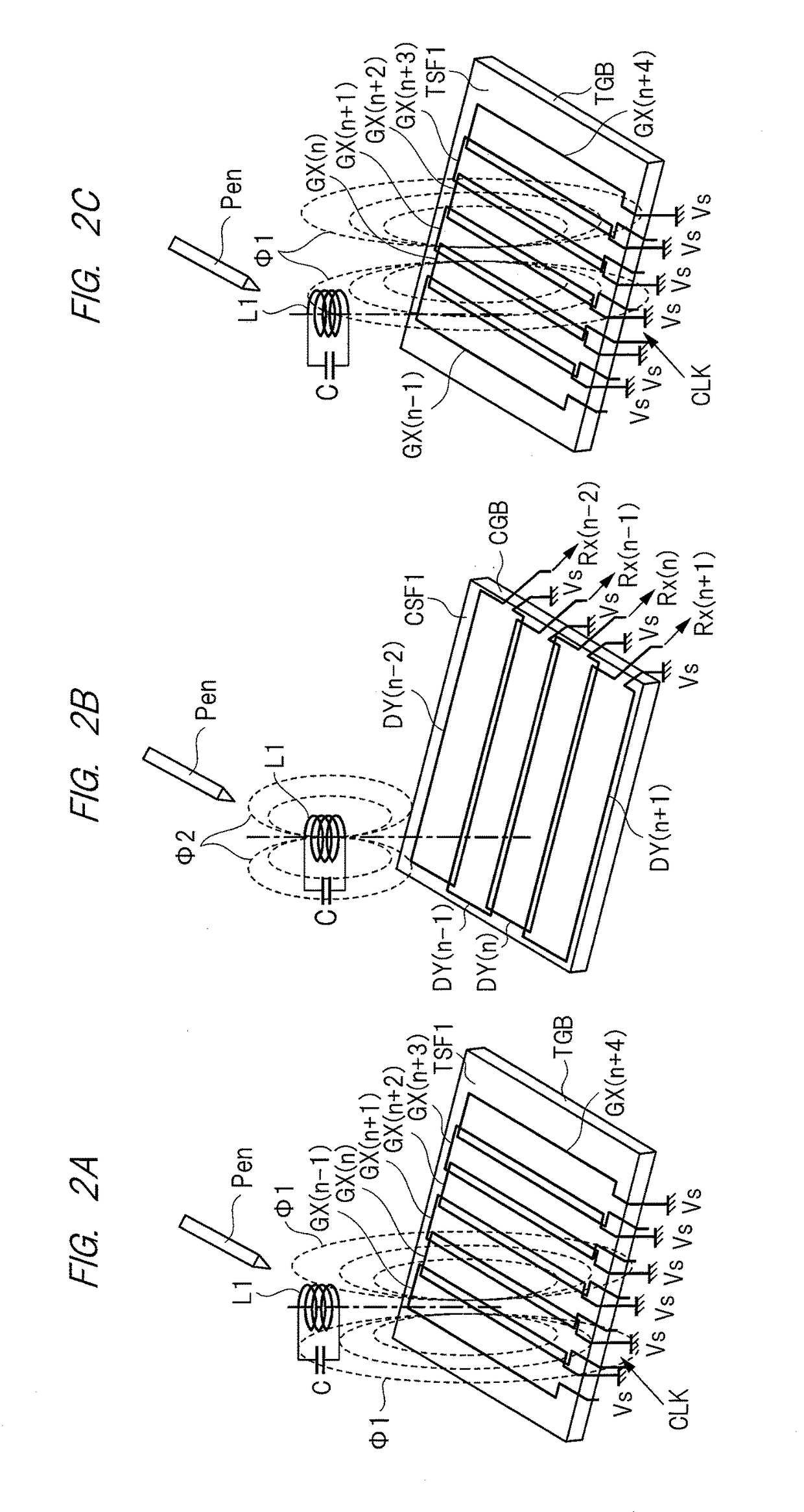
[0052]A first embodiment provides a liquid crystal display device with a touch detection function (hereinafter also referred to as a display device). The display device is capable of detecting both touch with a pen and touch with a finger. The display device is a so-called in-cell type display device obtained by integrating an detection device for detecting touch with a displaying device for displaying image. In other words, the display device of the first embodiment includes at least one of a substrate or an electrode that serves for both as a component of the liquid crystal display device and as a component of the touch panel. First, the basic configuration of the display device will be described. Next, principles of magnetic field detection (hereinafter also referred to as magnetic field touch detection or magnetic field touch detection by an electromagnetic induction method) detecting touch with a pen and electric field detection (hereinafter also referred to as electric field t...

second embodiment

[0271]A display device 1 according to a second embodiment will be described. In the second embodiment, points of difference from the above-described first embodiment will be mainly described.

[0272]FIG. 19 is a block diagram illustrating each configuration of the first scanner circuit pair SCL, the second scanner circuit pair SCR, the first selection drive circuit SDL, and the second selection drive circuit SDR according to the second embodiment. FIG. 19 is similar to FIG. 9 described above, and therefore, a point of difference will be mainly described.

[0273]The point of difference from the first embodiment illustrated in FIG. 9 is that connection destinations of the third selection signals AR(n) to AR(n+5) and connection destinations of the fourth selection signals BR(n) to BR(n+5) output from the second scanner circuit pair SCR, the connection destinations being in the second selection drive circuit SDR, are opposite.

[0274]FIG. 20 is a block diagram illustrating a configuration of ...


PUM

PropertyMeasurementUnit
drive voltageaaaaaaaaaa
electromagnetic induction methodaaaaaaaaaa
magnetic fieldaaaaaaaaaa

Abstract

An input detection device includes: a plurality of drive electrodes each of which includes a first end and a second end; a first scanner circuit and a second scanner circuit which select the first ends of the plurality of drive electrodes; a third scanner circuit and a fourth scanner circuit which select the second ends of the plurality of drive electrodes; and a controller which supplies a first drive voltage to the first end of a first drive electrode and to the second end of a second drive electrode and supplies a second drive voltage different from the first drive voltage to the second end of the first drive electrode and to the first end of the second drive electrode via the first scanner circuit, the second scanner circuit, the third scanner circuit, and the fourth scanner circuit.

Description

CROSS-REFERENCE TO RELATED APPLICATION[0001]The present application claims priority from Japanese Patent Application No. 2016-116230 filed on Jun. 10, 2016, the content of which is hereby incorporated by reference into this application.TECHNICAL FIELD OF THE INVENTION[0002]The present invention relates to an input detection device and an electronic device, and particularly relates to an input detection device and an electronic device with a touch detection function capable of detecting proximity of an external object.BACKGROUND OF THE INVENTION[0003]In recent years, an input detection device with a touch detection function, so-called a touch panel, capable of detecting proximity (hereinafter including contact) of an external object has drawn attention as an input detection device. The touch panel is mounted on a display device such as a liquid crystal display device or is integrated with the liquid crystal display device, and thus, the display device with a touch detection function ...

Claims


Application Information

Patent Timeline
Patent Type & Authority Applications(United States)
IPC IPC(8): G06F3/041G06F3/0354G02F1/1343G06F3/044G06F3/038G06F3/046G02F1/1333G09G3/36G02F1/1335G02F1/1368G06F3/047
CPCG06F3/0416G02F1/133514G02F1/134336G06F3/046G06F3/03545G06F3/038G06F3/0412G09G3/3677G09G3/3696G02F1/13338G06F2203/04108G06F2203/04106G06F3/047G02F1/1368G09G2300/0426G09G2310/08G02F2001/133302G02F1/133528G06F3/044G06F3/04164G06F3/04166G06F3/04184G06F3/0445G06F3/0446G02F1/133302
Inventor KATSUTA, TADAYOSHI
Owner JAPAN DISPLAY INC
Why Eureka
Try Eureka