Switching power supply device

a power supply device and power supply technology, applied in the direction of pulse technique, dc-dc conversion, power conversion systems, etc., can solve the problem of difficulty in keeping the amount of time required (the power supply restart time), and achieve the effect of shortening the restart time shortening the duration of latch protection operation, and reducing the power consumption of the power supply control devi

Active Publication Date: 2017-12-14
FUJI ELECTRIC CO LTD
View PDF0 Cites 6 Cited by
  • Summary
  • Abstract
  • Description
  • Claims
  • Application Information

AI Technical Summary

Benefits of technology

[0018]Meanwhile, the power consumption of the power supply IC 20 is reduced even further, and the consumption current of the IC control block 22 and the like during the latch protection operation is minimized. Thus, when the latch protection operation is performed, the time for the control power supply voltage Vcc, which decreased to the discharge threshold voltage Vdis as a result of the discharge of the capacitor C via the discharge circuit 26 described above, to thereafter further decrease to at least the operation stop voltage UVLO-off as a result of the power consumption of the IC block 22 and the like becomes longer.
[0019]Therefore, the amount of time required for the latch circuit 25 to reset during the latch protection operation will undoubtedly increase as a result of the increase in the capacitance of the capacitor C and the decreased power consumption of the power supply IC 20. Furthermore, since it is necessary to charge the capacitor C by restarting the power supply IC 20 after the latch circuit 25 has been reset, it is difficult to keep the amount of time required (the power supply restart time) from the start of the latch protection operation to the restart of the power supply IC 20 to within the above-mentioned 2 seconds.
[0027]According to the switching power supply device configured in such a manner, even if the capacitor connected to the power supply control device (power supply IC) has a large capacitance, the discharge circuit is caused to turn ON via a pulse signal of a prescribed cycle that is generated by a pulse generator upon receiving a latch signal generated when an anomaly is detected. As a result, it is possible to cause the control power supply voltage to decrease all the way to a prescribed discharge threshold voltage by causing the electric charge stored in the capacitor to be forcibly discharged via the discharge circuit. Thereafter, in a case in which the control power supply voltage has not decreased to the operation stop voltage, it is possible to cause the control power supply voltage to quickly decrease to the operation stop voltage by causing the electric charge remaining in the capacitor to be forcibly discharged once again via the discharge circuit by means of the pulse signal generated by the pulse generator.
[0028]As a result, even in a case in which a capacitor with a large capacitance is used and the power consumption of the power supply control device is further reduced, it is possible to shorten the duration of the latch protection operation of the power supply control device, or in other words, the amount of time required until the latch protection operation is canceled, when an anomaly is detected. Therefore, it is possible to sufficiently shorten the restart time of the power supply control device after the latch protection operation has been carried out. Thus, it is possible to keep the amount of time (power supply restart time) required from the latch protection operation, which occurs when an anomaly is detected, to the restart of the power supply control device to within the generally desired 2 seconds, for example.

Problems solved by technology

Furthermore, since it is necessary to charge the capacitor C by restarting the power supply IC 20 after the latch circuit 25 has been reset, it is difficult to keep the amount of time required (the power supply restart time) from the start of the latch protection operation to the restart of the power supply IC 20 to within the above-mentioned 2 seconds.

Method used


Image

  • Switching power supply device
  • Switching power supply device
  • Switching power supply device

Examples


Embodiment Construction

[0035]A switching power supply device according to an embodiment of the present invention will be explained hereafter with reference to the drawings.

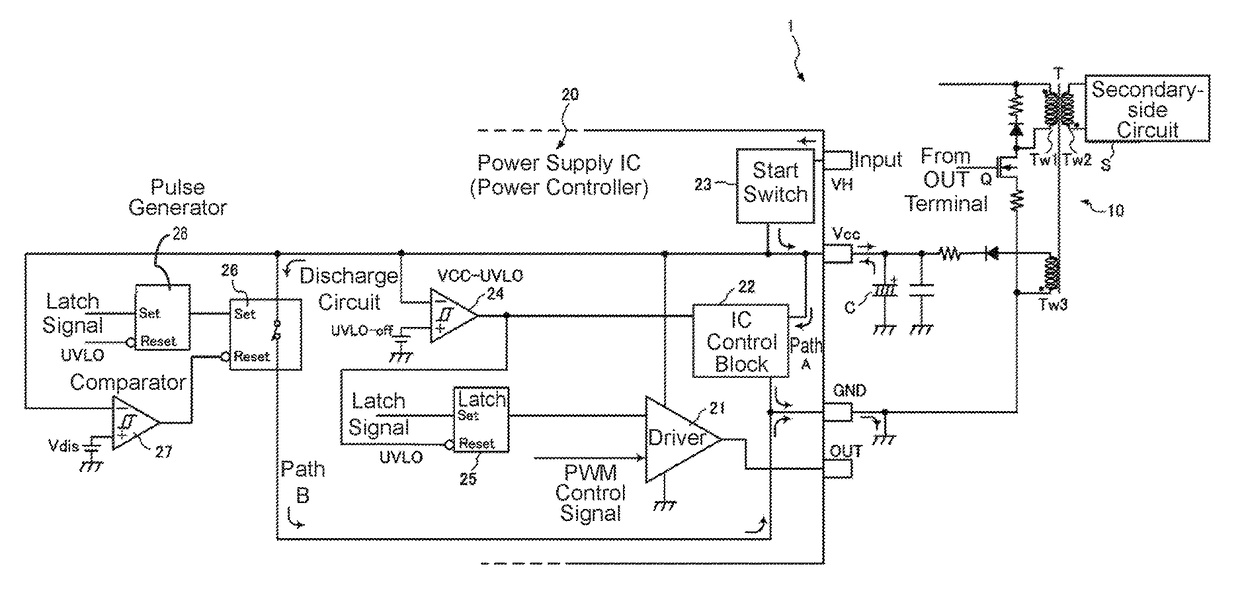
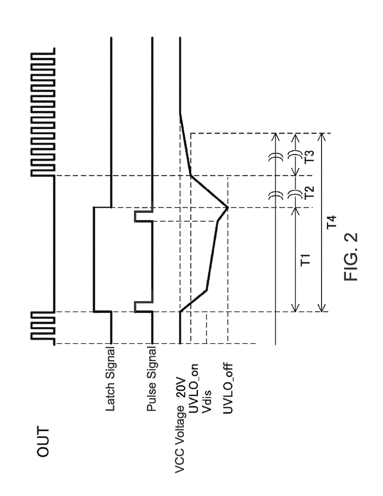
[0036]FIG. 1 is a schematic configuration diagram of the main components of a switching power supply device 1 according to an embodiment of the present invention. FIG. 2 shows the timing of a latch operation in a power supply control device (power supply IC) 20 of the switching power supply device 1 shown in FIG. 1. Parts similar to those of the conventional switching power supply device 1 shown in FIG. 3 are assigned the same reference characters and descriptions thereof are omitted.

[0037]This switching power supply device 1 is characterized by basically including, in the power source IC 20, a discharge circuit 26 for forcibly discharging electric charge stored in a capacitor C. In addition, the power supply IC 20 specifically includes a pulse generator 28 that is set by receiving a latch signal that sets a latch circuit 25 and then tu...


PUM


Abstract

A switching power supply device includes: a latch circuit to be set by a latch signal that is generated when an anomaly is detected, the latch circuit stopping the turning ON and OFF of the switching element when set by the latch signal; a pulse generator that receives said latch signal and generates a pulse signal at a prescribed cycle in response to said latch signal; a discharge circuit that is activated every time said pulse signal is provided so as to discharge electric charges stored in the capacitor; and a comparator for undervoltage protection that, when said control power supply voltage decreases to a prescribed operation stop voltage as said capacitor discharges, resets the latch circuit and the pulse generator, respectively.

Description

BACKGROUND OF THE INVENTIONTechnical Field[0001]The present invention relates to a switching power supply device that, after causing a power supply control device to perform a latch protection operation in accordance with a latch signal provided when an anomaly is detected, is able to quickly restart the power supply control device, which has stopped operating, thereby shortening the restart time of the power supply control device.Background Art[0002]A switching power supply device 1 that is able to achieve a prescribed direct current output voltage by switching an input voltage includes, as shown in FIG. 3, a switching power supply device main body 10 that is constructed using as a main component thereof a switching element Q, for example. The switching power supply device 1 further includes an integrated power supply IC 20 as a power supply control device that ON / OFF drives the switching element Q. The switching power supply device main body 10 includes: the switching element Q, w...

Claims


Application Information

Patent Timeline
Patent Type & Authority Applications(United States)
IPC IPC(8): H02M1/32H02M3/02H02H11/00H03K17/18H03K17/30
CPCH02M1/32H02H11/006H03K17/30H02M3/02H02M2001/322H03K17/18H02M1/08H02M1/36H02M3/33507H02M1/322
Inventor FUJII, MASANARI
Owner FUJI ELECTRIC CO LTD
Why Eureka
Try Eureka