Directional Microphone System

a microphone and microphone technology, applied in the field of directional microphone systems, can solve the problems of poor audio quality, poor sound quality, and inconvenient use, and achieve the effects of less room noise, convenient deployment, and improved sound quality

Inactive Publication Date: 2017-12-14
XEDIT CORP
View PDF6 Cites 1 Cited by
  • Summary
  • Abstract
  • Description
  • Claims
  • Application Information

AI Technical Summary

Benefits of technology

[0003]The directional microphone system of the invention includes a microphone assembly designed to be mounted from a ceiling or other raised surface through a reeling mechanism which is used to deploy the microphone to a lowered position just above eye level in order to obtain better audio signals. That is, the overall microphone system includes a servo-based reeler mounted to the ceiling or other raised surface mount, with the microphone assembly being attached to a cable which can be selectively extended or retracted from a housing of the servo-based reeler. With this arrangement, the microphone assembly can be readily deployed at an optimal height for audio reception, i.e., slightly above eye level height resulting in less room noise and improved audio presence. In particular in accordance with the invention, the microphone assembly includes an outer housing encapsulating multiple audio detection elements or capsules which are specifically angled relative to each other and the horizontal in order to optimize targeted audio reception.

Problems solved by technology

With these microphones positioned well above the individuals and relatively closer to the ceiling, typically a source of noise, the audio quality can also be compromised due to distance and impaired horizontal coverage.
At this high position the microphones often pick up more ambient or surrounding noise along with the audio from the intended speaker.
In addition, known microphones of this type tend to be quite large or bulky, generally being greater than two inches in diameter, resulting in a rather unpleasant eye-sore in what is intended to be an aesthetically pleasing environment.
Although it is possible to mount the microphones utilizing retractable reeling mechanisms so as to enable the height of the microphones relative to the individuals to be adjusted, audio quality would be compromised under these circumstances due to the known internal microphone element configuration and the overall bulky nature of these microphones makes lowering such microphones considerably less desirable.

Method used


Image

  • Directional Microphone System
  • Directional Microphone System
  • Directional Microphone System

Examples


Embodiment Construction

[0012]Detailed embodiments of the present invention are disclosed herein. However, it is to be understood that the disclosed embodiments are merely exemplary of the invention that may be embodied in various and alternative forms. The figures are not necessarily to scale, and some features may be exaggerated or minimized to show details of particular components. Therefore, specific structural and functional details disclosed herein are not to be interpreted as limiting, but merely as a representative basis for teaching one skilled in the art to employ the present invention. In addition, any specific numerical value listed herein includes a margin of error of + / −5%. Accordingly, an angle of 60° includes angles between 57° and 63°. The term “about” increases the margin of error to 10%.

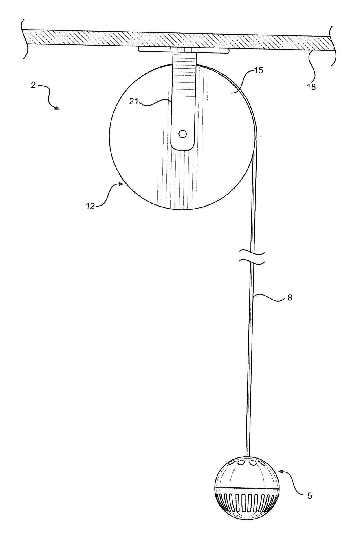
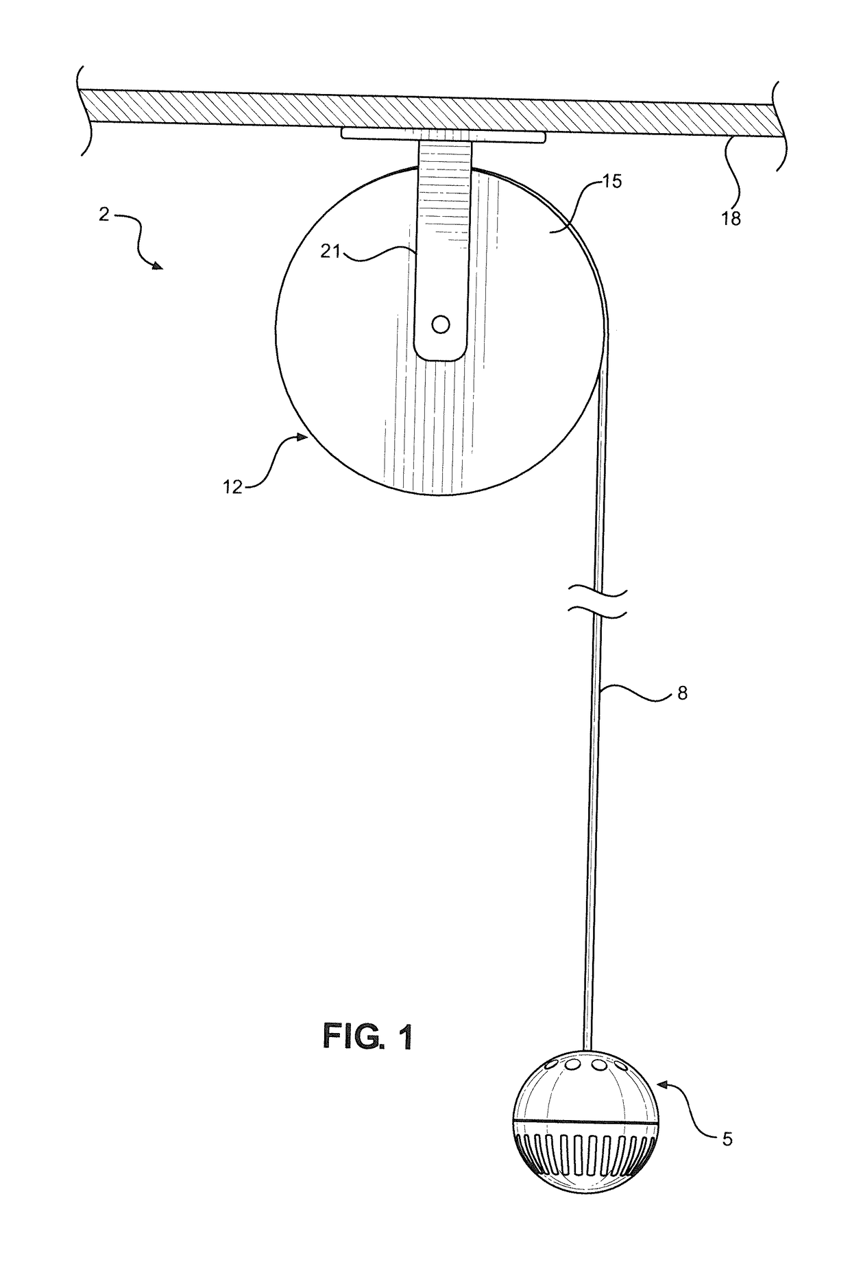
[0013]With initial reference to FIG. 1, a microphone system constructed in accordance with the present invention is generally indicated at 2. Microphone system 2 includes a microphone assembly 5 connected...


PUM


Abstract

A directional microphone system includes a microphone assembly designed to be mounted from a ceiling or other raised surface through a reeling mechanism used to deploy the microphone assembly to a lowered position, preferably just above eye level of a speaker. The microphone assembly includes an outer housing encapsulating multiple audio detection elements or capsules which are specifically angled relative to each other and the horizontal in order to optimize targeted audio reception. With a preferred arrangement, three audio detection (microphone) elements are secured through with a wishbone frame mounted in the outer housing, with each element being at about a 60° angle to the horizontal to provide enhanced horizontal coverage.

Description

BACKGROUND OF THE INVENTION[0001]The present invention pertains to the field of acoustics and, more particularly, to a directional microphone system for capturing audio signals. There are a number of multi-element microphones on the market. Typically, such microphones are employed in large meeting or lecture rooms, halls and the like of buildings where rather large groups of people gather for speaking engagements. Of particular concern to the present invention is the type of microphones generally referred to as “ceiling microphones”. In general, with these types of microphones, no distinction is made to differentiate microphones that are actually installed at the ceiling, or those that hang down for a short distance from the ceiling. Regardless, these microphones are intended to hang relatively high above the individuals speaking.[0002]For example, such a microphone system would typically be employed in a board room. When a meeting is conducted using the microphone system, various p...

Claims


Application Information

Patent Timeline
Patent Type & Authority Applications(United States)
IPC IPC(8): H04R1/40H04R1/08
CPCH04R1/406H04R2201/401H04R1/083H04R1/06H04R1/326H04R2201/021H04R2420/09
Inventor KARCZMER, CLAUDE M.
Owner XEDIT CORP
Why Eureka
Try Eureka