System and method for intraoperative surgical planning

a surgical planning and intraoperative technology, applied in the field of intraoperative surgical planning, can solve the problems of dislodged bone fragments, difficult to repair traumatic damage to joints, and other problems, and achieve the effect of improving surgical efficiency, improving surgical efficiency, and improving surgical efficiency

Active Publication Date: 2017-12-21
ZIMMER INC
View PDF1 Cites 16 Cited by
  • Summary
  • Abstract
  • Description
  • Claims
  • Application Information

AI Technical Summary

Benefits of technology

[0004]The present inventors have recognized, among other things, that a problem to be solved can include providing trauma surgeons with tools that allow for accessible pre-operative and intraoperative planning for joint reconstruction operations. The background briefly introduces some challenges presented by traumatic injuries to the shoulder joint, which is used as the exemplary joint during the majority of the following discussion. The shoulder joint provides an excellent vehicle for describing the capabilities of the systems and methods discussed below. The systems and methods are described here principally for anatomical shoulder arthroplasty, however the systems and methods are similarly applicable to a reverse shoulder arthroplasty. Additionally, the systems and methods are similarly applicable to other joints of the body, such as wrist, knee, hip, or elbow joints. In particular, certain hip replacement systems utilize a compatible method implantation and would benefit from implementation of concepts discussed herein. Additionally, the type of intraoperative planning discussed below is new for joint reconstruction and / or replacement surgeries.

Problems solved by technology

The complexity of the shoulder joint makes any traumatic damage to the joint particularly difficult to repair.
Fractures can result in dislodged bone fragments and other challenging issues for the orthopedic surgeon to resolve, often with limited pre-operative planning.

Method used


Image

  • System and method for intraoperative surgical planning
  • System and method for intraoperative surgical planning
  • System and method for intraoperative surgical planning

Examples


examples

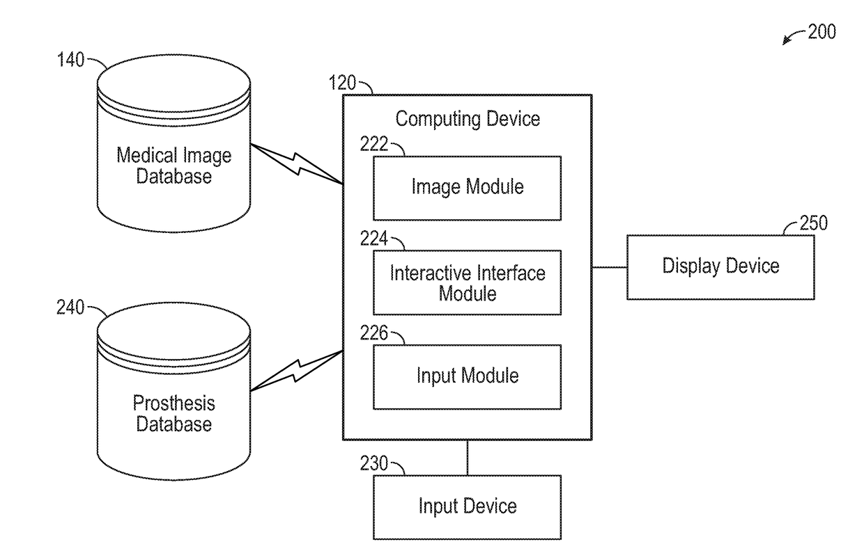
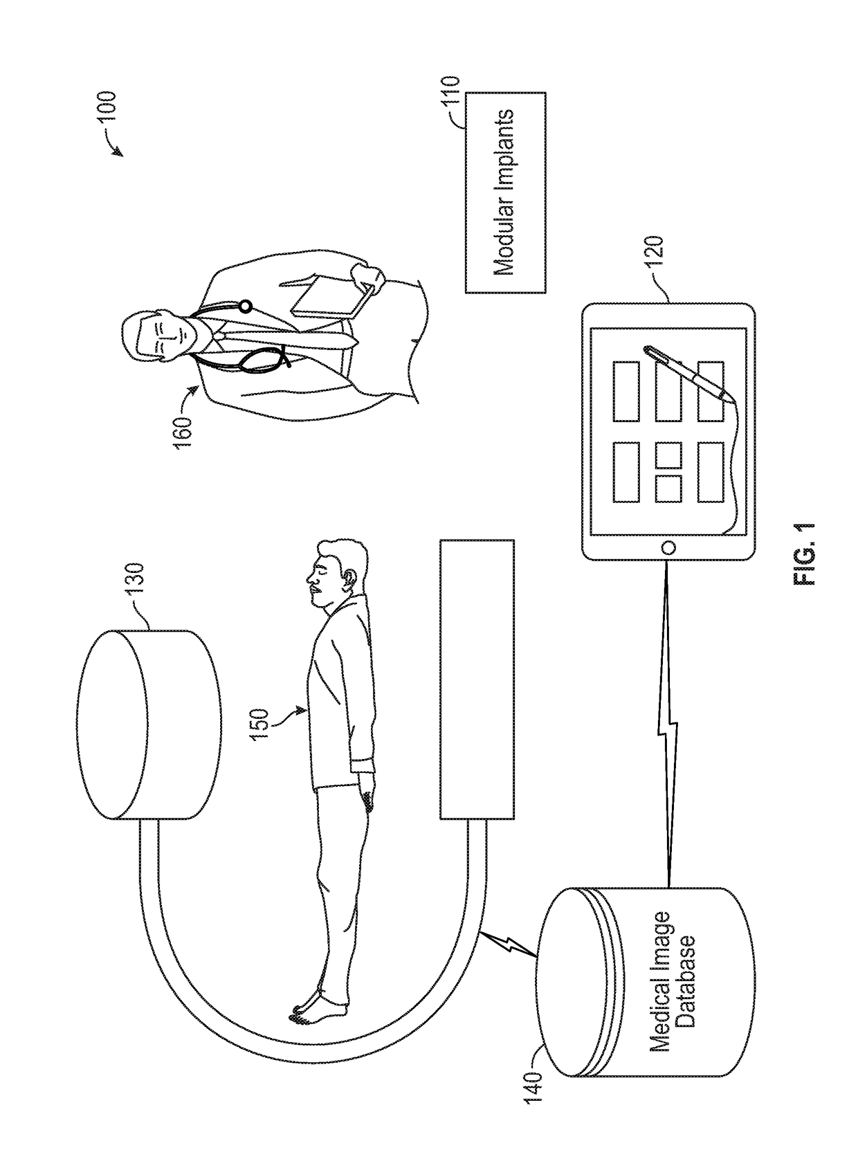
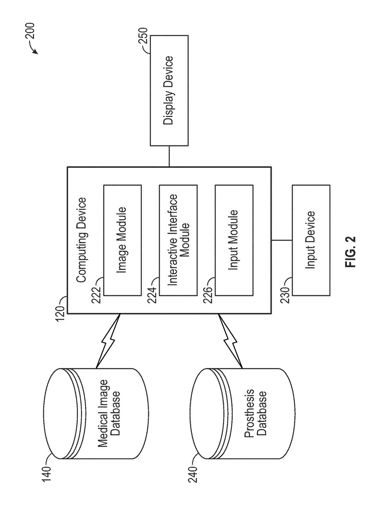
[0073]Example 1 describes an intraoperative surgical planning technique operating on a computing device available within the operating room. The technique in this example can being by accessing, on a computing device operating an intraoperative surgical planning interface, a first medical image providing a first view of a joint within a surgical site. The technique can continue by receiving, within the intraoperative surgical planning interface, selection of a first component of a modular prosthetic device implanted in the first bone of the joint. The technique further includes operations to display, within the intraoperative surgical planning interface, a graphical representation of the first component of the modular prosthetic device overlaid on the first medical image. The described technique also includes updating the graphical representation of the first component based on receiving, within the intraoperative surgical planning interface, positioning inputs representative of an ...


PUM


Abstract

The subject matter includes systems, methods, and prosthetic devices for joint reconstruction surgery. A computer-assisted intraoperating planning method can include accessing a first medical image providing a first view of a joint within a surgical site as well as receiving selection of a first component of a modular prosthetic device implanted in the first bone of the joint. The method continues by displaying a graphical representation of the first component of the modular prosthetic device overlaid on the first medical image, and updating a graphical representation of the first component based on receiving positioning inputs representative of an implant location of the first component relative to landmarks on the first bone visible within the first medical image. The method concludes by presenting a selection interface enabling visualization of additional components of the modular prosthetic device virtually connected to the first component and overlaid on the first medical image.

Description

CLAIM OF PRIORITY[0001]This application claims the benefit of U.S. Provisional Patent Application Ser. No. 62 / 351,564, filed on Jun. 17, 2016, the benefit of priority of which is claimed hereby, and which is incorporated by reference herein in its entirety.BACKGROUND[0002]The shoulder joint is a complex joint with the scapula, clavicle and the humerus all coming together to enable a wide range of movement, at least in a properly functioning joint. In a properly functioning shoulder joint the head of the humerus fits into a shallow socket in the scapula, typically referred to as the glenoid. Articulation of the shoulder joint involves movement of the humeral head in the glenoid, with the structure of the mating surfaces and surrounding tissues providing a wide range of motion.[0003]The complexity of the shoulder joint makes any traumatic damage to the joint particularly difficult to repair. Fractures can result in dislodged bone fragments and other challenging issues for the orthoped...

Claims


Application Information

Patent Timeline
Patent Type & Authority Applications(United States)
IPC IPC(8): A61B34/10A61F2/30A61F2/46G06F19/00A61B34/00A61B90/00A61F2/40
CPCA61B34/10A61F2/30942A61F2/4657A61B34/25G06F19/3437A61B2034/108A61B2034/256A61F2002/4658A61B2034/252A61B2090/365A61F2/4014A61F2002/4022A61F2/4059A61B2090/363A61F2/40A61F2002/3008A61B2090/067A61B2090/061A61B2034/102A61B2034/105A61B2090/3966A61B2017/00203A61B2017/00207A61B2017/00216A61B2034/2048A61B2034/254A61F2002/4633G16H50/50A61F2002/4632
Inventor BISCHOFF, JEFFREY E.HUCKY, JOANNA
Owner ZIMMER INC
Why Eureka
Try Eureka