Method for Optimizing the Production of a Rotor Spinning Machine

Active Publication Date: 2017-12-21
RIETER INGOLSTADT GMBH
View PDF44 Cites 3 Cited by
  • Summary
  • Abstract
  • Description
  • Claims
  • Application Information

AI Technical Summary

Benefits of technology

The present invention allows for continuous tracking of yarn production and adjustment of delivery speed to achieve maximum production capacity, regardless of high thread breakage rates. Furthermore, individual delivery speed and rotor speed can be set for each spinning unit, optimizing production capacity of the entire rotor spinning machine.

Problems solved by technology

However, such an increase in the production speed is limited by the increase in the delivery speed, since an increase in the delivery speed also always entails a reduction in machine efficiency, which in turn reduces production capacity.
For example, a higher delivery speed also leads to an increase in the thread breakage frequency, and thus to a temporary failure of the spinning unit.
Since, when the maximum permissible thread breakage rate is exceeded, the rotational speed of the spinning rotors is always reduced and production is thus limited, the yarn production capacity of the rotor spinning machine cannot be utilized in an optimum manner.

Method used


Image

  • Method for Optimizing the Production of a Rotor Spinning Machine
  • Method for Optimizing the Production of a Rotor Spinning Machine
  • Method for Optimizing the Production of a Rotor Spinning Machine

Examples


Embodiment Construction

[0031]Reference will now be made to embodiments of the invention, one or more examples of which are shown in the drawings. Each embodiment is provided by way of explanation of the invention, and not as a limitation of the invention. For example features illustrated or described as part of one embodiment can be combined with another embodiment to yield still another embodiment. It is intended that the present invention include these and other modifications and variations to the embodiments described herein.

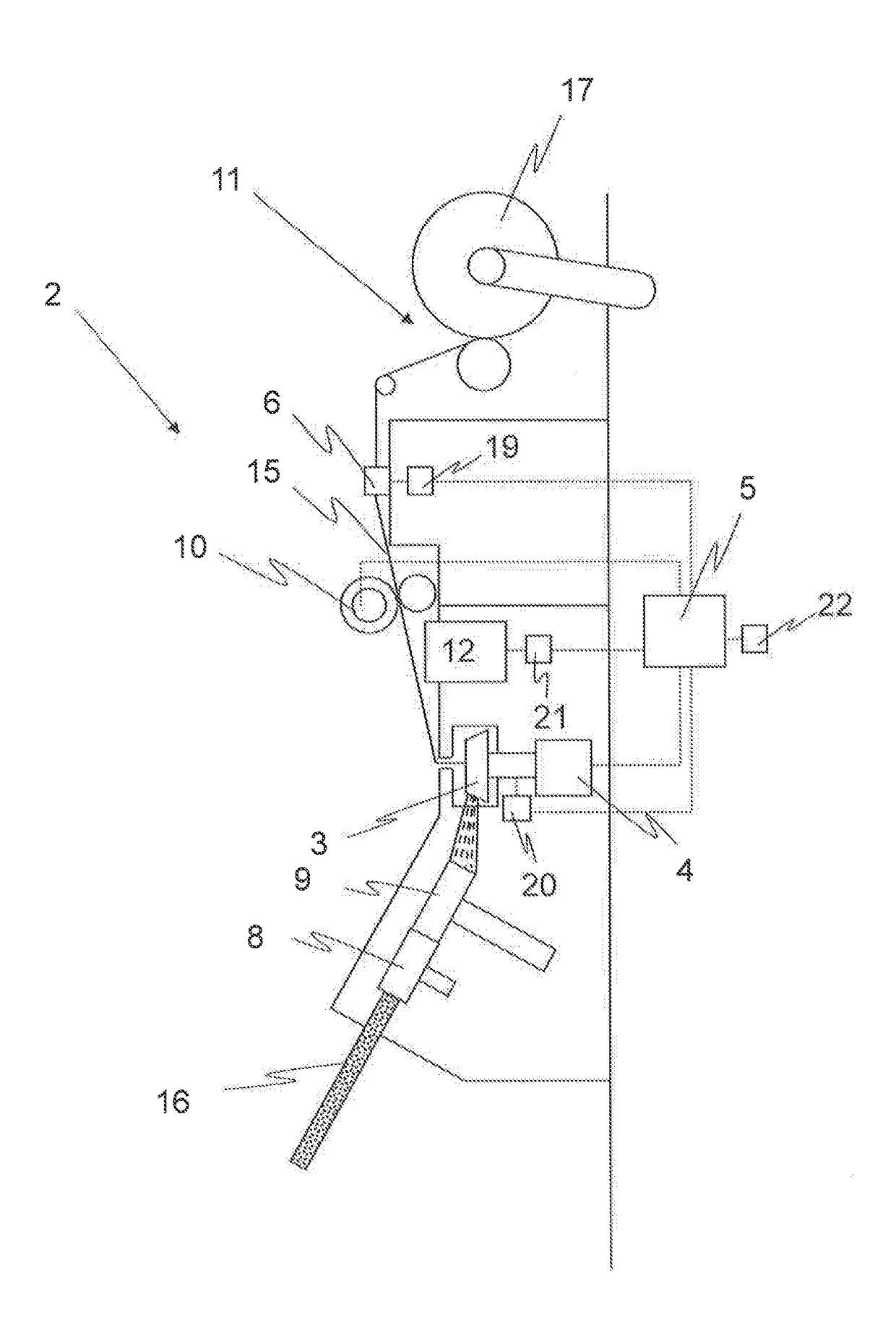
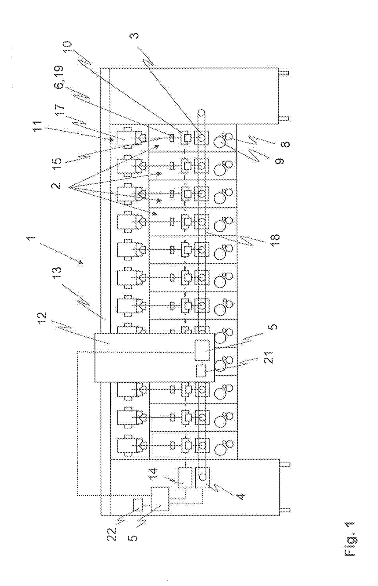
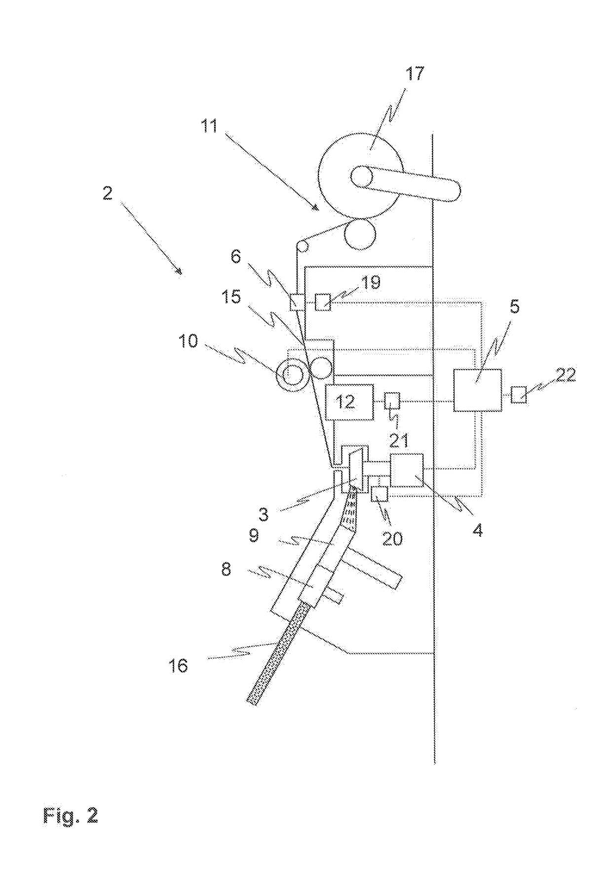
[0032]FIG. 1 shows a rotor spinning machine 1 with a multiple number of spinning units 2 arranged side by side, each having a spinning rotor 3 as a spinning element. Here, a fiber material 16 (see FIG. 2), which is opened into individual fibers in a opening device 9 and fed to the spinning rotor 3, is fed to the spinning units 2 in a conventional manner by means of a feed device 8. The yarn 15 produced in the spinning rotor 3 is subsequently drawn off by a draw-off device 10 at a d...


PUM

PropertyMeasurementUnit
Speedaaaaaaaaaa
Energyaaaaaaaaaa

Abstract

A method optimizes production of a rotor spinning machine having a plurality of identical spinning units, with each spinning unit having a spinning rotor driven by a rotor drive at a rotor speed to produce yarn at a delivery speed. A permissible range with a minimum delivery speed and a maximum delivery speed for the delivery speed of the spinning units is specified. Operation of the spinning units is started with a starting delivery speed within the permissible range. Current production capacity of the spinning units or the rotor spinning machine is continuously calculated. Current delivery speed of the yarn is regulated as a function of the current production capacity in such a manner that a maximum production capacity is achieved. A rotor spinning machine in accordance with method is also provided.

Description

FIELD OF THE INVENTION[0001]The present invention relates to a method for optimizing the production of a rotor spinning machine with a multiple number of identical spinning units each having a spinning rotor. During the operation of the rotor spinning machine, the spinning rotors are driven by at least one rotor drive and each rotate with one rotor speed, whereas each of the spinning units provides a yarn with one delivery speed. The invention also relates to a corresponding rotor spinning machine.BACKGROUND[0002]In modern rotor spinning machines, there is always the demand for the highest possible production capacity, in order to be able to optimally utilize the spinning machine and to operate it in a cost-effective manner. Therefore, attempts were made in the prior art to be able to increase the rotor speed and thus the delivery speed, and thus to achieve higher production. However, such an increase in the production speed is limited by the increase in the delivery speed, since an...

Claims


Application Information

Patent Timeline
IPC IPC(8): D01H4/44D01H1/14
CPCD01H1/14D01H4/44D01H4/08D01H4/12
Inventor STEPHAN, ADALBERT
Owner RIETER INGOLSTADT GMBH
Why Eureka
Try Eureka