Acoustic lens system

a technology of acoustic lens and acoustic beam, which is applied in the direction of loudspeakers, instruments, diaphragm construction, etc., can solve the problems of presenting design challenges, loudspeakers may not be positioned or oriented in a manner, and the use of loudspeakers, so as to reduce the radiating dimensions of the diaphragm, effectively reduce the radiating dimensions of the high-frequency beam, and widen the high-frequency

Active Publication Date: 2008-01-08
HARMAN INT IND INC
View PDF73 Cites 27 Cited by
  • Summary
  • Abstract
  • Description
  • Claims
  • Application Information

AI Technical Summary

Benefits of technology

[0018]The system may also effectively reduce the high-frequency radiating dimensions of a diaphragm included in a loudspeaker. The high-frequency radiating dimensions may be reduced to widen the high-frequency coverage of the loudspeaker without affecting other operating characteristics. Specifically, a directivity-modifying acoustic lens may be used to partially block radiating portions of a loudspeaker. The radiating portions may be partially blocked to effectively reduce the radiating dimensions of the diaphragm at high frequencies. In addition, the coverage or beam width angle of the diaphragm may be widened. At mid to low frequencies, the acoustic lens may have minimal effect on the loudspeaker sensitivity, power handling and maximum sound pressure level.

Problems solved by technology

Many types of design and manufacturing challenges present themselves with regard to the manufacture of the electro-dynamic planar loudspeakers.
Accordingly, the conductor presents design challenges since it must be capable of carrying current and is preferably low in mass and securely attached to the film even at high power and high temperatures.
Often, however, space limitations in the listening environment prohibit the use of a loudspeaker in the audio system that possesses the preferred directivity pattern for the system's design.
For example, the amount of space and the particular locations in a listening environment that are available for locating and / or mounting the loudspeakers of the audio system may prohibit including a particular loudspeaker that exhibits the directivity pattern intended by the system's designer.
Also, due to the environment's space and location restraints, a loudspeaker may not be capable of being positioned or oriented in a manner that is consistent with the loudspeaker's directivity pattern.
Consequently, the performance of the audio system in that environment cannot be achieved as intended.
Unfortunately, this large size results in a high-frequency beam width angle or coverage that may be too narrow for its intended application.

Method used


Image

  • Acoustic lens system
  • Acoustic lens system
  • Acoustic lens system

Examples


Embodiment Construction

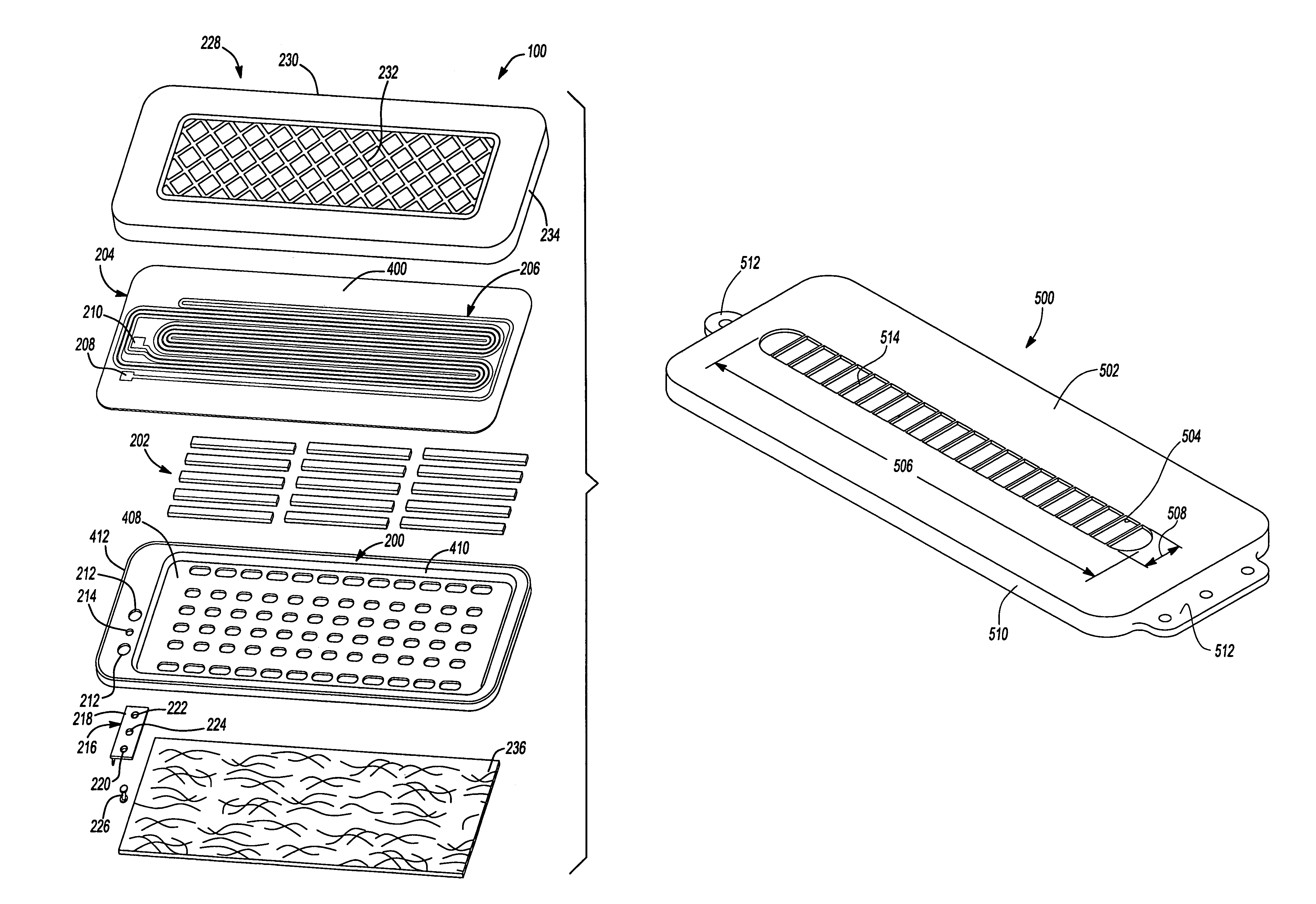
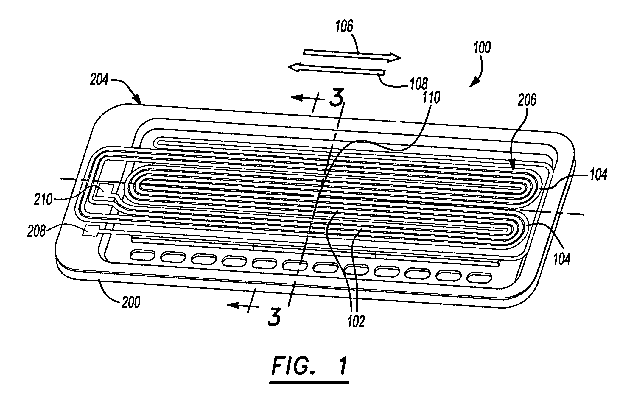
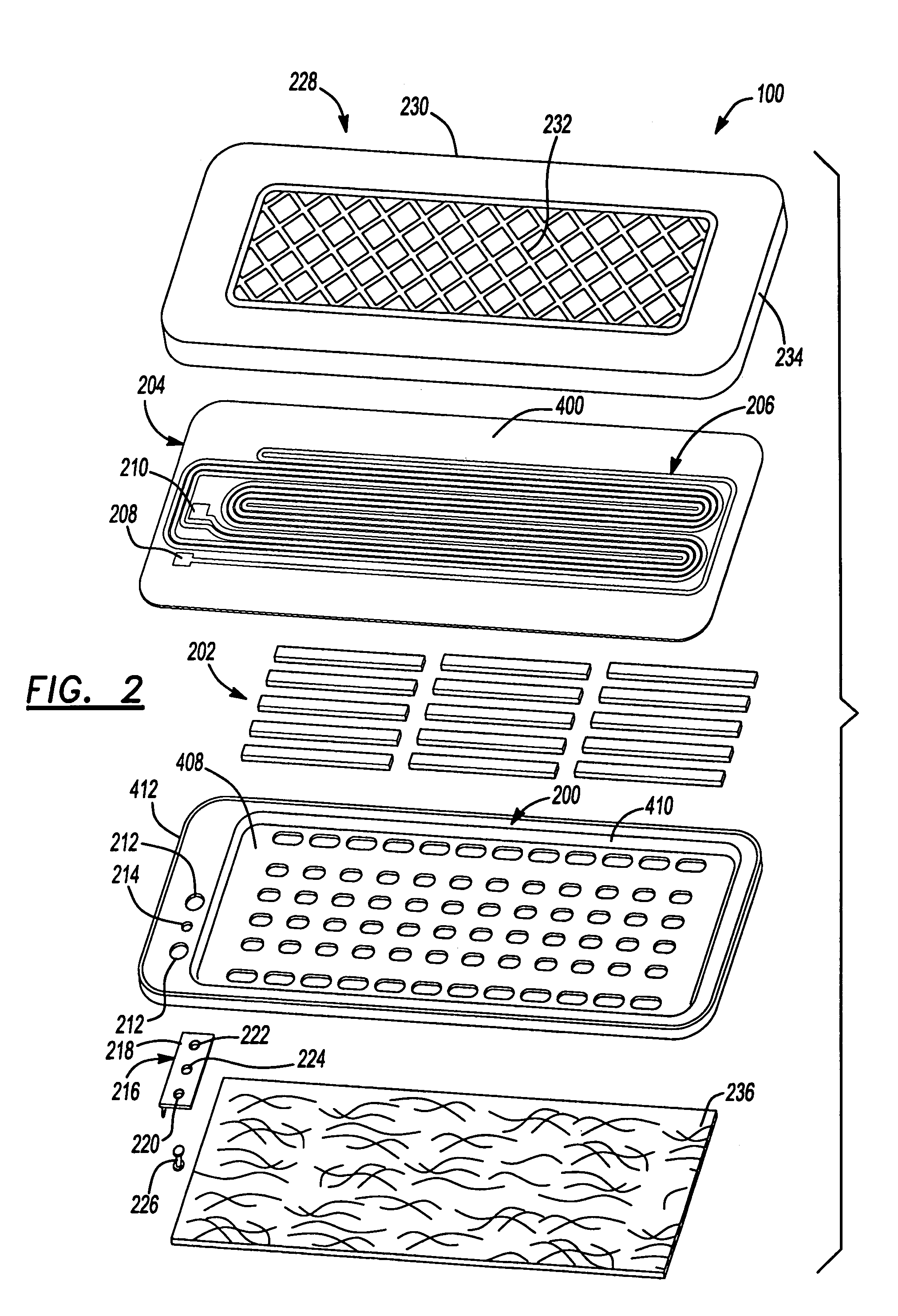
[0033]FIGS. 1-4 illustrate a flat panel loudspeaker 100 that includes a frame 200, a plurality of high energy magnets 202 and a diaphragm 204. Frame 200 provides a structure for fixing magnets 202 in a predetermined relationship to one another. Magnets 202 may be positioned to define five rows of magnets 202 with three magnets in each row as illustrated. The rows are arranged with alternating polarity such that fields of magnetic flux are created between each row. Once the flux fields have been defined, diaphragm 204 may be fixed to frame 200 along its periphery.

[0034]FIG. 4 illustrates a diaphragm 204 that includes a thin film 400 having a first side 402 and a second side 404. First side 402 is coupled to frame 200. An adhesive 406, such as an adhesive that is curable by exposure to radiation may secure the film to the frame 200. To provide a movable membrane capable of producing sound, diaphragm 204 is mounted to the frame in a state of tension and is spaced apart a predetermined ...


PUM


Abstract

A loudspeaker includes a frame, a magnet coupled to the frame and a diaphragm secured to the frame. An acoustic lens may be positioned in front of the diaphragm. An aperture extends through the acoustic lens. The acoustical directivity pattern of the loudspeaker may be modified by the acoustic lens to improve the uniformity of the off axis vs. on axis sound pressure level.

Description

CROSS-REFERENCE TO RELATED APPLICATIONS[0001]This application claims the benefit of U.S. Provisional Application No. 60 / 443,699, filed on Jan. 30, 2003. The disclosure of U.S. Provisional Application No. 60 / 443,699 is incorporated by reference in its entirety.BACKGROUND OF THE INVENTION[0002]1. Field of the Invention[0003]The invention relates to electro-dynamic planar loudspeakers, and more particularly, to ways of controlling and / or enhancing the acoustical directivity pattern of an electro-dynamic planar loudspeaker.[0004]2. Related Art[0005]In the field of electro-dynamic planar loudspeakers, a diaphragm in the form of a thin film is attached in tension to a frame. An electrical circuit is applied to the surface of the diaphragm in the form of electrically conductive traces. A magnetic field is generated by a magnetic source that is mounted adjacent to the diaphragm. Typically, the magnetic source is formed from permanent magnets mounted within the frame. The diaphragm is caused...

Claims


Application Information

Patent Timeline
Patent Type & Authority Patents(United States)
IPC IPC(8): G10K11/08H04R1/28H04R7/06H04R1/34H04R7/04H04R9/04
CPCH04R1/345H04R7/04H04R9/047H04R2201/34H04R2400/11
Inventor HUTT, STEVEN WSTEERE, JOHN FKEELE, JR., D. B
Owner HARMAN INT IND INC
Why Eureka
Try Eureka