Multifunctional cargo hold system

a cargo hold and multi-functional technology, applied in the direction of loading/unloading vehicle arrangment, load accommodation, transportation items, etc., can solve the problems of complex change in the configuration of the cargo hold, time-consuming, etc., and achieve the effect of easy retrofi

Active Publication Date: 2014-09-23
AIRBUS OPERATIONS GMBH
View PDF23 Cites 3 Cited by
  • Summary
  • Abstract
  • Description
  • Claims
  • Application Information

AI Technical Summary

Benefits of technology

[0004]The object of the invention is to provide a cargo bay system for an aircraft that is easy to retrofit.
[0011]In another exemplary embodiment of the invention, the retaining rail is a seat rail. Using a seat rail makes it possible to draw upon already present, tested components that are approved in aeronautical engineering. This permits a simple and rapid implementation in practice.
[0012]It is advantageously provided that the loading positions extend over at least 70 percent of the length of the cargo bay floor. The region just cited even more preferably encompasses 80 percent of the length of the cargo bay floor. This region even more preferably encompasses 90 percent of the length of the cargo bay floor, and the latter region even more preferably encompasses 95 percent of the length of the cargo bay floor. Providing all means necessary for installation purposes over this length makes it possible to achieve a maximum level of flexibility in equipping and retrofitting the cargo bay. No larger-scale conversions, cable installations or the like are required. This makes it possible to quickly respond to modifications requested by the customer, and the loading configuration can even be varied from flight to flight without any greater outlay, depending on what the aircraft is being used for. In this conjunction, the cargo bay system can offer a universal platform consisting of retaining rails, retaining points and arrangements (e.g., electrical cables, ductwork for cables, drainage lines), so as to enable the already mentioned loading configuration via quick-release fasteners (e.g., snap & click, plug & play, etc.).
[0016]An advantageous exemplary embodiment provides that the cargo bay system is equipped with a rolling unit with at least one rolling cylinder, a quick-release fastener that can be detached without tools, with which the rolling unit can be detachably secured to a retaining rail of the cargo bay system. As a consequence, rolling units do not have to be provided at each location of the cargo bay floor, but rather only in the locations required for this purpose. In addition, this exemplary embodiment supports the advantages from the flexible retrofitting of the cargo bay.
[0017]These advantages can be realized even more effectively if the rolling unit also has a pivoting attachment hook. In addition, this results in an increased percentage of standardized components, and the expanded rolling unit serves as a uniform option for equipping the various loading configurations.

Problems solved by technology

The disadvantage here is that changes in the cargo bay configuration are complex and time intensive.

Method used


Image

  • Multifunctional cargo hold system
  • Multifunctional cargo hold system
  • Multifunctional cargo hold system

Examples


Embodiment Construction

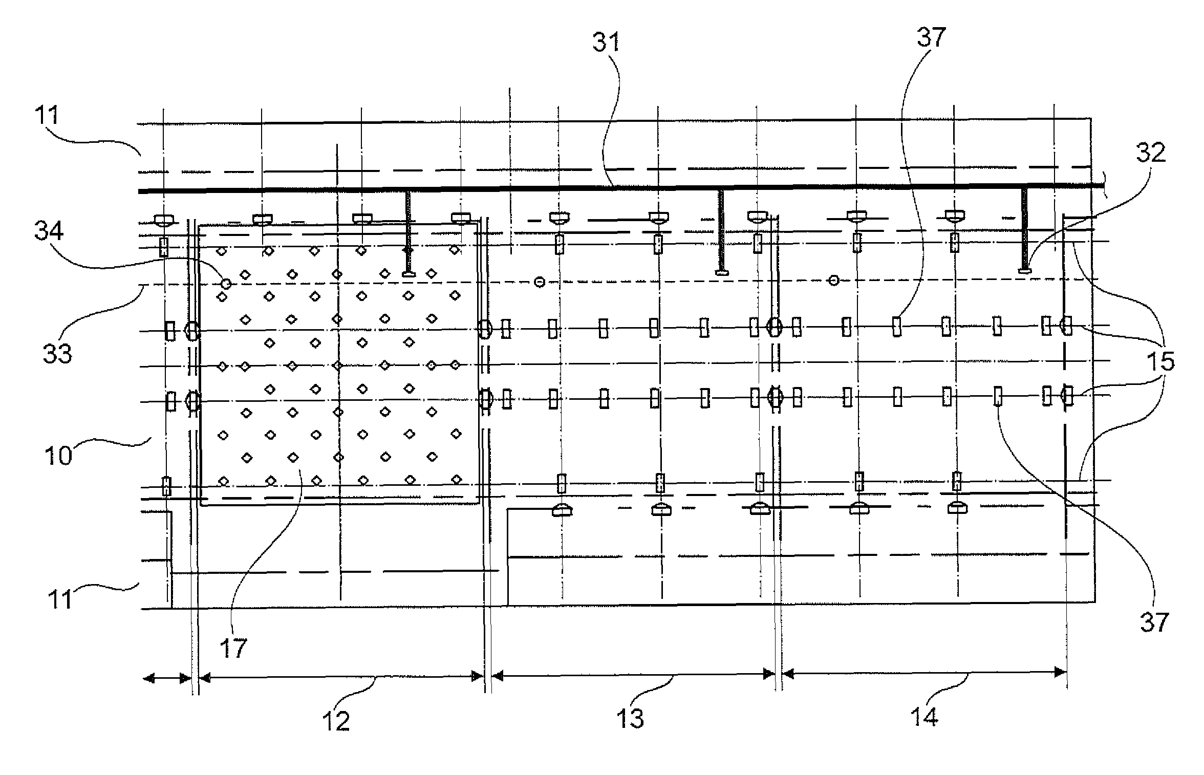
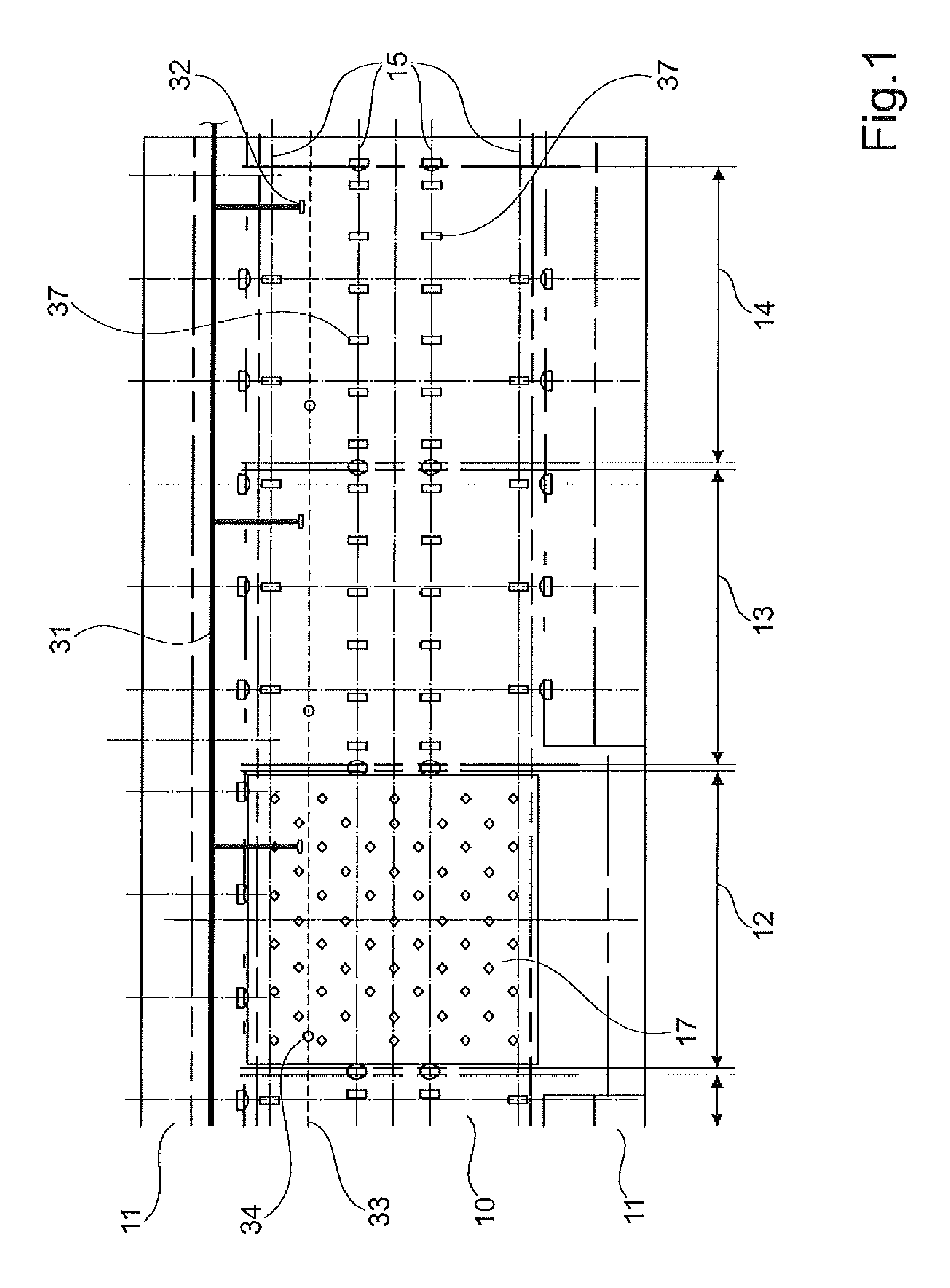
[0035]FIG. 1 shows a cargo bay system according to an exemplary embodiment of the invention. In a sectionally depicted cargo bay involving a lower deck cargo bay, which shows the cargo bay floor 10 and cargo bay walls 11 proceeding at an upward incline from the latter, the cargo bay floor 10 is divided into various loading positions 12-14. Mounted on the cargo bay floor 10 and running in the longitudinal direction of the aircraft are retaining rails 15, which are preferably the kind of retaining rails also used for installing seats in the aircraft cabin, meaning commercially available seat rails. These retaining rails 15 are preferably embedded in the cargo bay floor 10, so that the upper side of the retaining rails 15 abuts flush with the cargo bay floor 10, but it is also conceivable that they be installed on the surface of the cargo bay floor 10 without being embedded. This exemplary embodiment provides four rows of retaining rails 15, wherein two rows run along the sides of the ...


PUM


Abstract

A multifunctional cargo hold system for an aircraft includes a cargo hold floor; a retainer rail fitted to the cargo hold floor, suitable for the assembly of units for rolling and / or fixing of loaded elements. The units have a variable assembly with regard to the longitudinal direction of the retainer rail. The cargo hold system has a number of cargo positions, suitable for accommodating elements of the group, including a net for partitioning the cargo hold, a standard container, a palette, a telescopic system, an underfloor catering container, an underfloor rest space, a conveyor of fixed length and a conveyor of variable length, wherein each load position can accommodate at least four of the elements.

Description

REFERENCE TO RELATED APPLICATION[0001]The present application is a national phase entry under 35 U.S.C. §371 of International Application No. PCT / EP2009 / 063335, filed Oct. 13, 2009, published in German, which claims the benefit of German Patent Application No. 10 2008 052 337.2, filed Oct. 20, 2008 and of U.S. Provisional Patent Application No. 61 / 196,747, filed Oct. 20, 2008, the entire disclosures of which applications are incorporated herein by reference.FIELD OF THE INVENTION[0002]The invention relates to a multifunctional cargo bay system for an aircraft, and an aircraft with such a cargo bay system.TECHNOLOGICAL BACKGROUND[0003]Cargo bays of aircraft are used in various configurations. While the primary function is here to stow luggage, cargo bays are also used to accommodate catering, break areas or waste. The most familiar configurations in this conjunction are standard containers or pallets (“cargo loading”), loads comprised of bulk mixed cargo (“bulk”), a telescope system ...

Claims


Application Information

Patent Timeline
Patent Type & Authority Patents(United States)
IPC IPC(8): B64C1/20B64D9/00B64D11/04
CPCB64D9/003B64C1/20B64D11/04
Inventor PANZRAM, UWESCHOEN, HANS-JOACHIMMALARCZUK, MANFREDGRABOW, THOMAS
Owner AIRBUS OPERATIONS GMBH
Why Eureka
Try Eureka