
Retrofit light fixture mounting device

a technology for retrofitting and light fixtures, which is applied in the direction of fixed installation, semiconductor lamp usage, lighting and heating apparatus, etc., can solve the problems of short life inefficient number of lumens generated per electrical watt consumed, and easy burnout or breakage of incandescent light sources, so as to achieve maximum light levels and distribution, maximum light level and aesthetic

Inactive Publication Date: 2006-02-21
AUBREY TRUMAN
View PDF2 Cites 12 Cited by
  • Summary
  • Abstract
  • Description
  • Claims
  • Application Information

AI Technical Summary

Benefits of technology

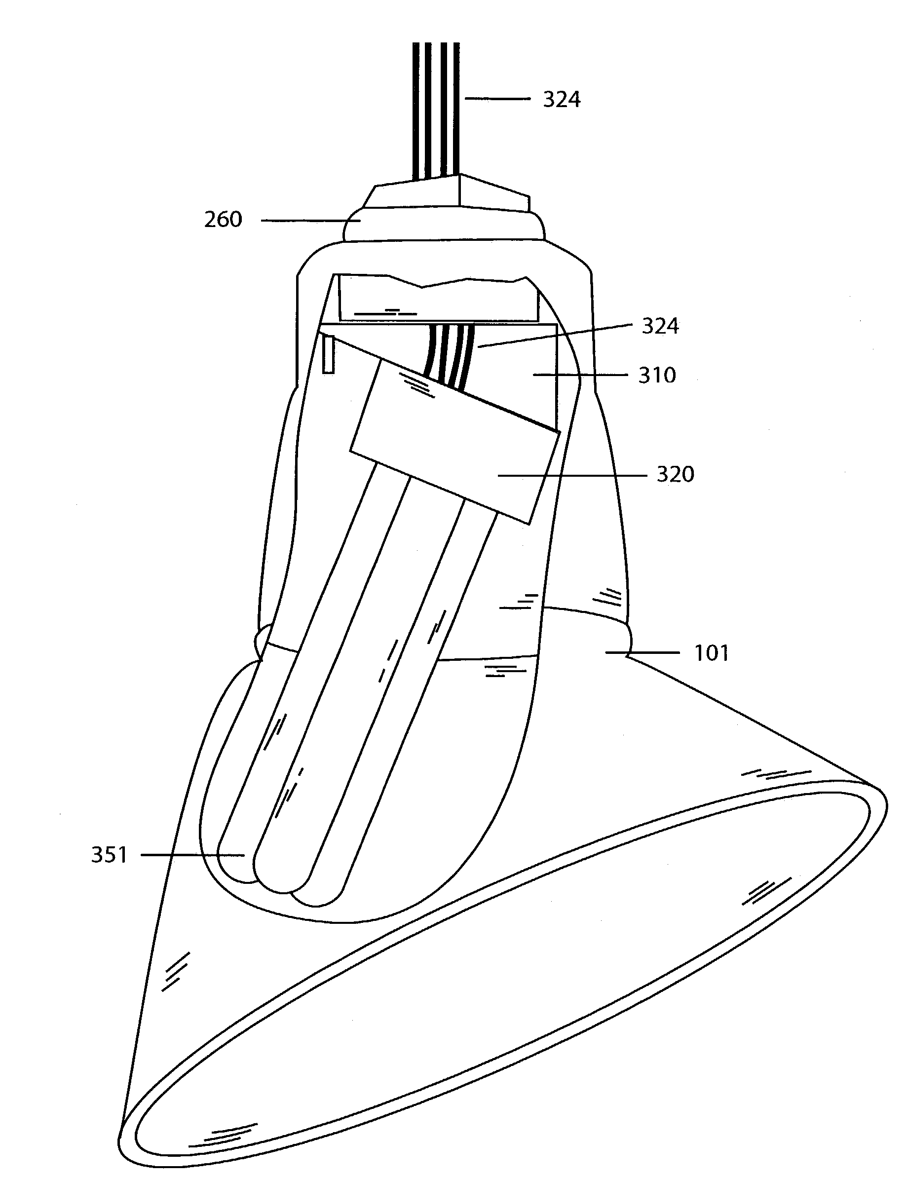
[0011]This invention is directed to a retrofit kit which permits fluorescent or similar light bulbs to replace incandescent light bulbs in an angled reflector, wall-wash, stem mounted style fixture and position the relatively long fluorescent lamp at an angle of approximately 30° and allows the lamp to be mounted somewhat off center from the perpendicular existing incandescent socket at an angle to maximize maximum light levels and distribution onto merchandise displayed on walls while using the existing fixture reflector to shield the fluorescent from objectionable side light glare. The kit includes a pair of interacting base members with cooperating angles formed therein in order to provide an offset support for a light source socket to fit into the existing fixture. Alternatively, a socket-mounting bracket with rotational adjustment slots designed to adjust the fluorescent socket in each fixture can be used to accomplish maximum light level and aesthetic effect.

Problems solved by technology

However, incandescent light sources have a short life and are inefficient.
The number of lumens generated per electrical watt consumed is not economical and is generally on the order of 14 to 17 lumens per watt.
In addition, these types of light sources generally use a thin filament which glows when heated by electrical power, and tends to burn out or break rather easily.
Also, incandescent light sources tend to generate a large amount of heat which is given off into the surrounding area.
Thus, incandescent light sources tend to be energy consumers and wasters.
However, these alternative light sources are normally not interchangeable with incandescent lamps or bulbs.
The “Edison-base” coupling which is common on the ordinary incandescent lamp and light fixture will not accept standard fluorescent fittings.
Although single ended high-pressure sodium and metal halide lamps are available which can be screwed into an Edison-base socket, they cannot be successfully operated because, typically, arc discharge lamps require a ballast to operate the lamp.
Furthermore, inasmuch as the ballast may be relatively large, it usually cannot be mounted within the interior of the fixture.

Method used


Image

  • Retrofit light fixture mounting device
  • Retrofit light fixture mounting device
  • Retrofit light fixture mounting device

Examples


Embodiment Construction

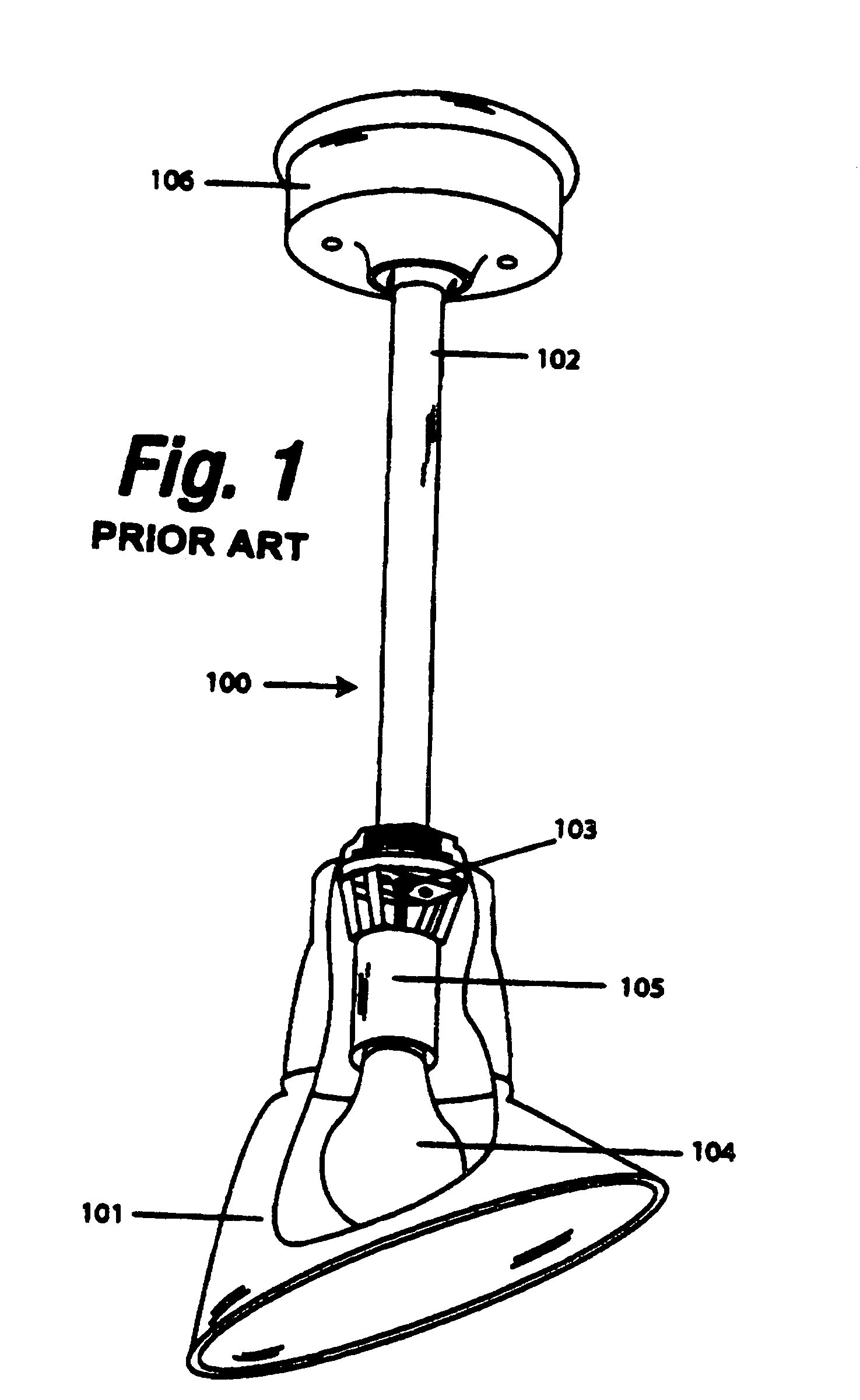
[0020]Referring now to FIG. 1, there is shown a partially broken away view of an existing incandescent light fixture 100 with an angled reflector 101 mounted on a stem 102. A conventional incandescent light source or bulb 104 is threadedly engaged with a conventional Edison-type socket 105. Electrical conductors 103 are threaded through the stem 102 and connected to a suitable power source in a junction box (not shown) within the structure or within a canopy 106 which can be ceiling or wall mounted.

[0021]It is seen that in this type of fixture, for example similar to an Abolite AD series fixture, the light source 104 is positioned to be completely received within the reflector 101 in an up and down 90° vertical position in order to be efficiently positioned relative to the “bulge” or curved portion of the reflector 101. This arrangement, typically, has been determined by the shape of the conventional light source 104.

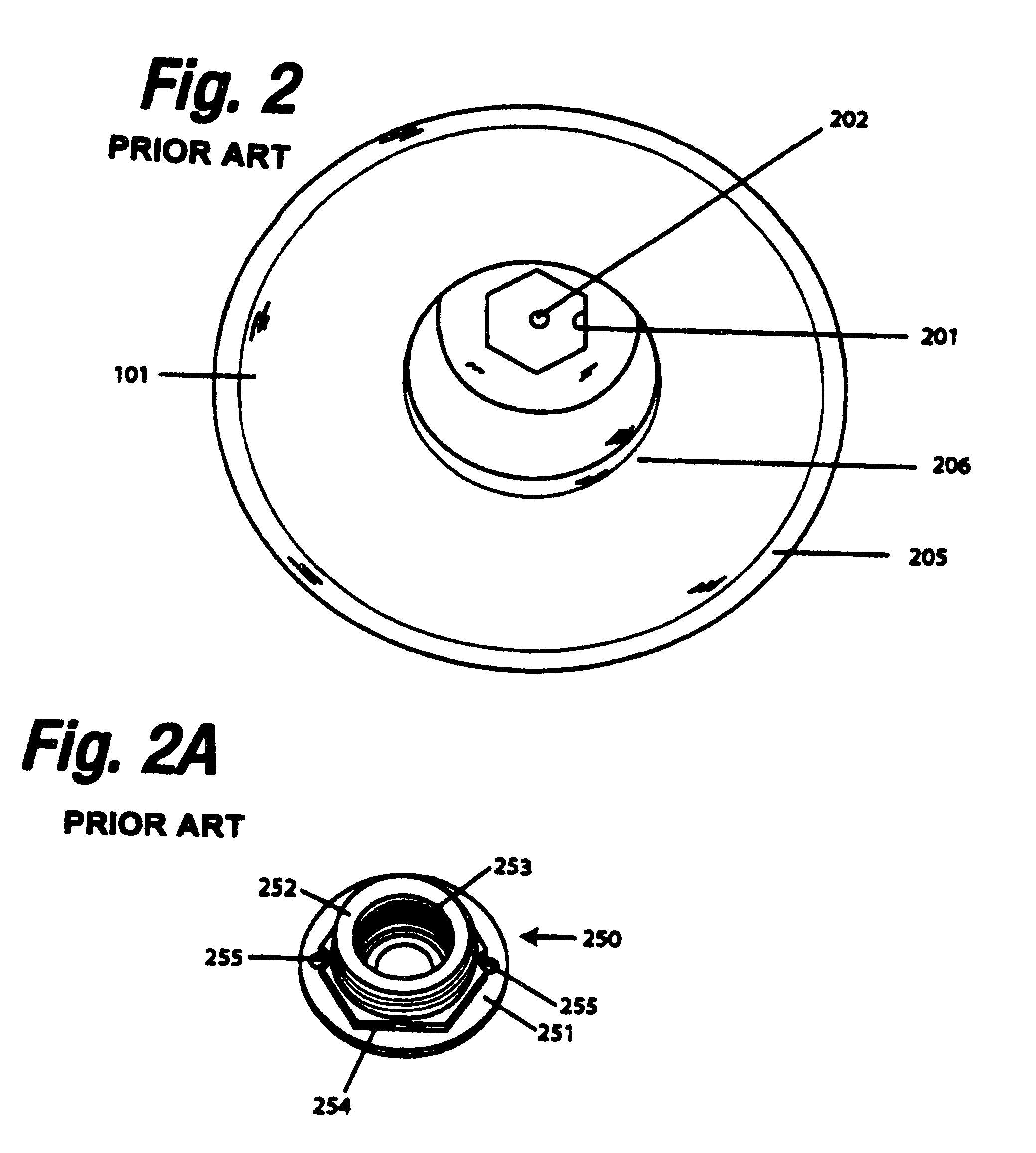
[0022]Referring now to FIG. 2, there is shown a representative end...


PUM


Abstract

A retrofit unit which is used for replacing conventional incandescent light bulbs with fluorescent light bulbs in existing lighting fixtures of the ceiling or wall mounted type.

Description

BACKGROUND[0001]1. Field of the Invention[0002]This invention is directed to a retrofit unit for light fixtures, in general, and to a retrofit unit which permits fluorescent or similar light bulbs to replace incandescent light bulbs in an angled reflector, stem mounted, goose neck style fixtures, in particular.[0003]2. Prior Art[0004]There are many types of light fixtures which are known in the art. These include recessed fixtures, surface mounted fixtures, track-light fixtures and the like, including goose neck fixtures, specifically fixtures manufactured by Abolite or perhaps others. Most of the known light fixtures of this type use incandescent light sources therein. However, incandescent light sources have a short life and are inefficient. The number of lumens generated per electrical watt consumed is not economical and is generally on the order of 14 to 17 lumens per watt.[0005]In addition, these types of light sources generally use a thin filament which glows when heated by el...

Claims


Application Information

Patent Timeline
IPC IPC(8): F21S8/00
CPCF21V19/0095Y02B20/386Y02B20/30
Inventor AUBREY, TRUMAN
Owner AUBREY TRUMAN
Learn More