Geogrid sand fence

a sand fence and geogrid technology, applied in metal-working equipment, protective construction, construction, etc., can solve the problems of sand accumulation on wellsites and roads located in these desert areas, requiring costly excavation procedures, and currently used methods, so as to minimize safety hazards and costs, easy to repair, and easy to standardize

Active Publication Date: 2015-04-21
SAUDI ARABIAN OIL CO
View PDF28 Cites 1 Cited by
  • Summary
  • Abstract
  • Description
  • Claims
  • Application Information

AI Technical Summary

Benefits of technology

[0008]In view of the foregoing, embodiments of the present invention provide a sand fence / apparatus and methods to control sand or other particulate matter movement, to protect roads and other facilities from such encroachment. Embodiments of the present invention provide a sand fence made of an ultraviolet light resistant High Density Polyethylene geogrid mesh polymer material, which is durable, easy to repair, and easy to standardize, and which can be positioned to minimize the safety hazards and costs associated with mechanical sand excavation procedures. The polymer material, according to various embodiments of the present invention, has a plurality of apertures therein sized, shaped, and distributed to provide a porosity, for example, of approximately 50%, which was found through testing to maximize sand deposit volume and distribution. A 50% porosity and circular opening, for example, was found to provide gentle slowing down of wind velocity so that sand load carried by the wind will drop on the leeward of the sand fence.
[0009]According to various embodiments of the present invention, the height of the sand fence can also be substantially taller than conventional sand fences to maximize control of sand movement, which can be adjusted in response to sand accumulation in order to further and continuously maximize control of sand movement. According to embodiments of the present invention, the combination of porosity, aperture shape, height, structural weight, and structural composition of the sand fence can beneficially provide a sand fence having optimal sand movement control and accumulation, particularly on the leeward side of the fence.
[0010]Specifically, a sand fence for depositing sand particles moved by wind currents, according to an embodiment of the present invention, can include a plurality of support members to secure the sand fence to a surface. The plurality of support members can be positioned to extend downward into the surface a first preselected distance, and positioned to extend upwardly from the surface a second preselected distance. The plurality of support members can include at least two end post members and at least two, but typically a multitude of, intermediate post members. A set of four or so tensioning wires can extend between each pair of adjacent intermediate post members to enhance strength and stability. The sand fence can also include a fencing material attached to the plurality of support members and / or tensioning wires. The fencing material can include a flexible high density polyethylene geogrid mesh having a porosity in a range of between approximately 40% and 60% (e.g., 50%) and having a plurality of e.g., circular, apertures each having a diameter in the range of between, for example, approximately 6 mm and 10 mm, and positioned so that the sand fence gently reduces a speed of the wind currents as the wind currents move through the fencing material such that sand accumulation on a leeward side of the sand fence is substantially optimized. The High Density Polyethylene geogrid mesh can include approximately 2% finely divided carbon black, for example, to enhance the durability of the material. In order to help prevent buildup on the windward side of the sand fence, the fencing material can be suspended above the surface in a range of between approximately 10 cm and 20 cm, for example.

Problems solved by technology

Facilities, wellsites and roads located in these desert areas suffer from sand accumulation caused by these movements.
Over time, sand dunes and sand sheets accumulate, requiring costly excavation procedures.
There are a number of disadvantages to the currently used methods.
Oil and chemical stabilization will only hold the sand underneath the surface and will not stop it from traveling over the top of the surface.
Vegetation typically requires at least two years to become permanently established, requires irrigation, and may be eaten by desert animals.
Barrier-type fences, by their nature, quickly become buried, thus rendering them ineffective.
Wood slat and fabric “sand fences” are not durable, are susceptible to damage and theft, and are very hard to repair.
Further, due to structural and environmental limitations, the wood slat and fabric “sand fences” generally have a maximum height of approximately one meter, and cannot be extended in height.
Accordingly, although not as quickly as barrier-type fences, the wood slat and fabric “sand fences” are, nevertheless, often relatively quickly buried by the sand over time, thus rendering them ineffective.
This results in a requirement to either excavate the sand or install a replacement “sand fence.” Further, although studies conducted by the inventors revealed that sand moved by wind currents that is subject to being accumulated through use of a sand fence, only extends from between the zero level and about the two meter level, as noted above, such conventional “sand fences” extend only up to approximately one meter, and thus, allow a great deal of sand to be moved, unimpeded, over the top of the conventional “sand fence.” Additionally, the wood needed to build the wood slat “sand fences” often must be imported, or is not otherwise locally available.

Method used


Image

  • Geogrid sand fence
  • Geogrid sand fence
  • Geogrid sand fence

Examples


Embodiment Construction

[0029]The present invention will now be described more fully hereinafter with reference to the accompanying drawings, which illustrate embodiments of the invention. This invention may, however, be embodied in many different forms and should not be construed as limited to the illustrated embodiments set forth herein. Rather, these embodiments are provided so that this disclosure will be thorough and complete, and will fully convey the scope of the invention to those skilled in the art. Like numbers refer to like elements throughout.

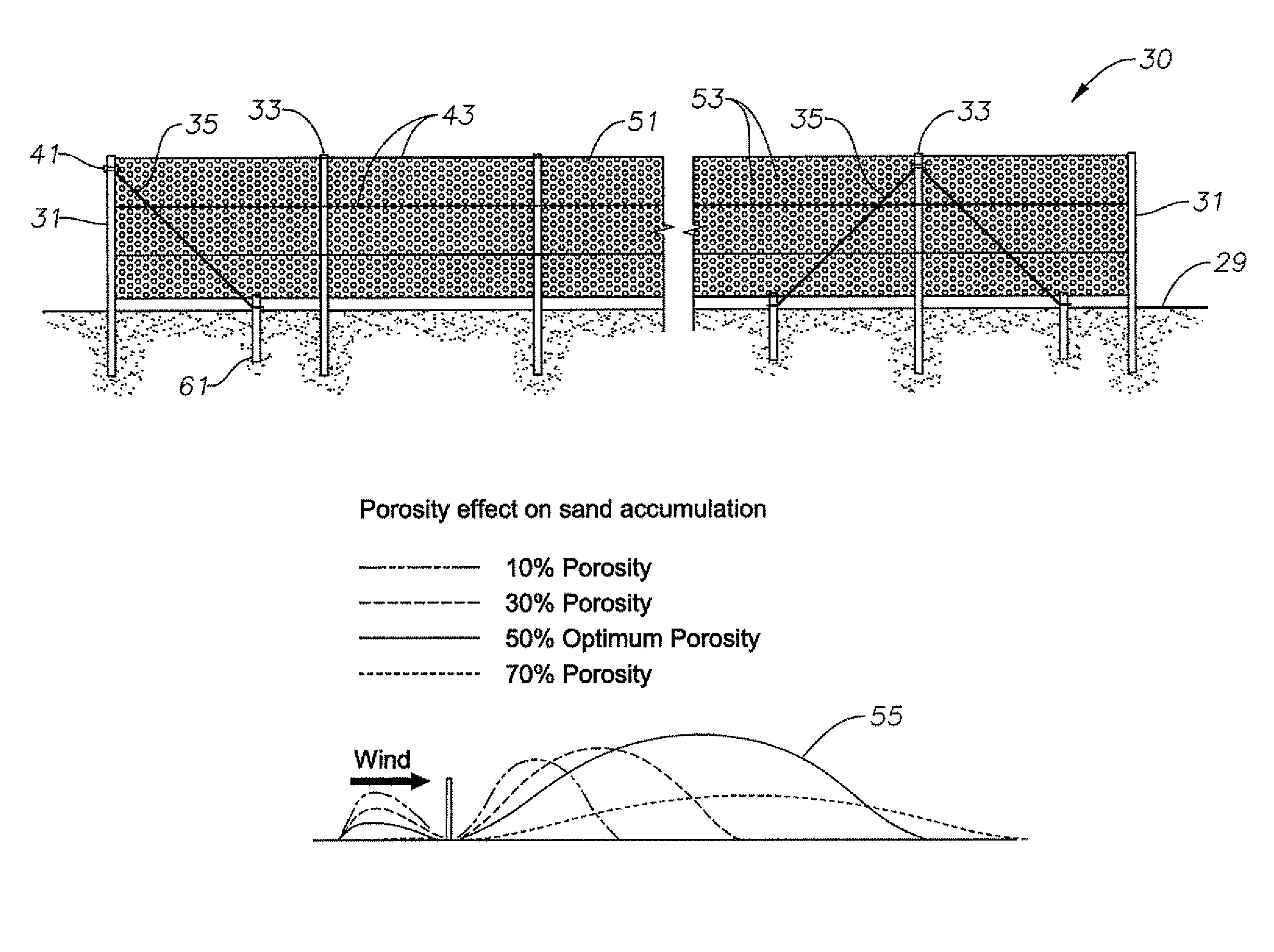
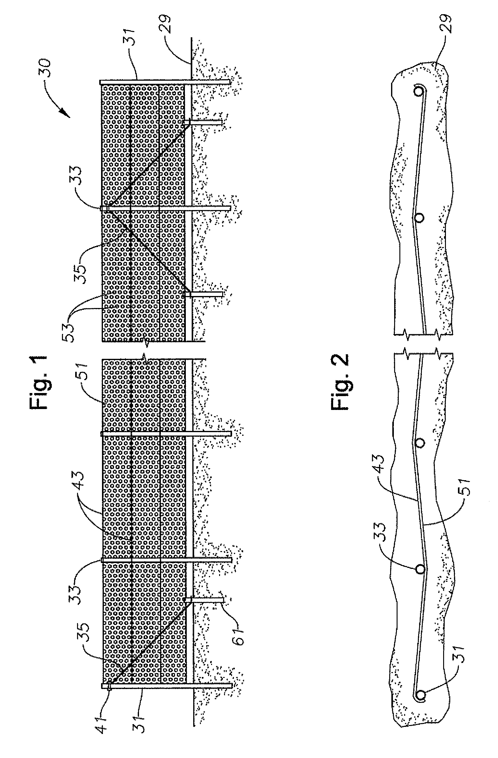
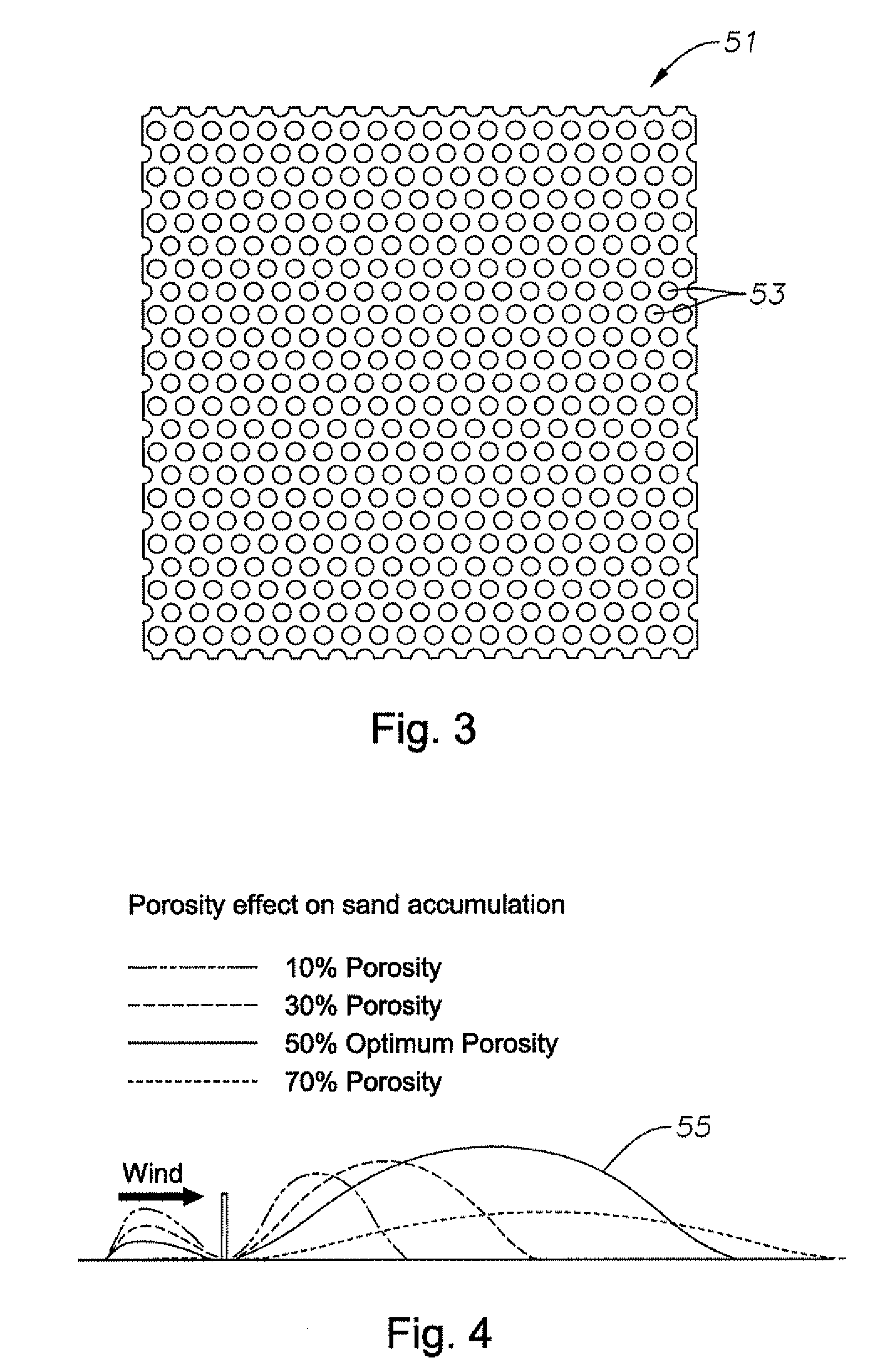
[0030]As shown in FIGS. 1-12, embodiments of the present invention provide a sand fence including a High Density Polyethylene (HDPE) mesh sand fence material with specific material properties including, for example, material type, aperture opening size and geometry, porosity, and specific height. Such specific material properties and configuration properties including, for example, position with respect to the prevailing wind, are based on field studies pe...


PUM

PropertyMeasurementUnit
porosityaaaaaaaaaa
diametersaaaaaaaaaa
heightaaaaaaaaaa

Abstract

A geogrid sand fence for depositing matter moved by wind currents and related methods, are provided. A geogrid sand fence for the control of sand or other particulate matter movement can include support members carrying a fencing material. The fencing material can include a High Density Polyethylene geogrid mesh material having apertures distributed to provide approximately a 50% porosity to maximize sand deposit volume. The geogrid mesh material has sufficient structural weight to be employed with a height of approximately two meters, which can be adjusted to maintain maximum effectiveness.

Description

BACKGROUND[0001]1. Field of Invention[0002]This invention relates in general to particle movement control and, in particular, to a fence for precipitating, depositing, and accumulating matter moved by wind currents to protect roads and facilities from sand encroachment.[0003]2. Description of Related Art[0004]Control of particulate matter, such as sand, is a major concern in many areas of the world. Over one-third of Saudi Arabia, for example, is covered by sand, which has hundreds of sand storms, annually. Facilities, wellsites and roads located in these desert areas suffer from sand accumulation caused by these movements. Over time, sand dunes and sand sheets accumulate, requiring costly excavation procedures.[0005]There are a number of solutions employed to try to prevent such sand accumulation. These solutions include, for example, oil and chemical stabilization, vegetation, barrier fences, and wood slat or fabric sand fences. The concept of a “sand fence” is to reduce the wind ...

Claims


Application Information

Patent Timeline
Patent Type & Authority Patents(United States)
IPC IPC(8): B21D47/00E01F7/02
CPCE01F7/02Y10T29/49623
Inventor KAHTANI, NASSER SGROSCH, JONATHAN J
Owner SAUDI ARABIAN OIL CO
Why Eureka
Try Eureka