
System and method for programming and/or operating an automation system with execution-oriented combination logic

a combination logic and automation system technology, applied in the field of system and method for programming automation systems and computer program products, can solve problems such as inadequate data consistency, and achieve the effect of high data consistency

Inactive Publication Date: 2007-06-12
SIEMENS AG
View PDF5 Cites 2 Cited by
  • Summary
  • Abstract
  • Description
  • Claims
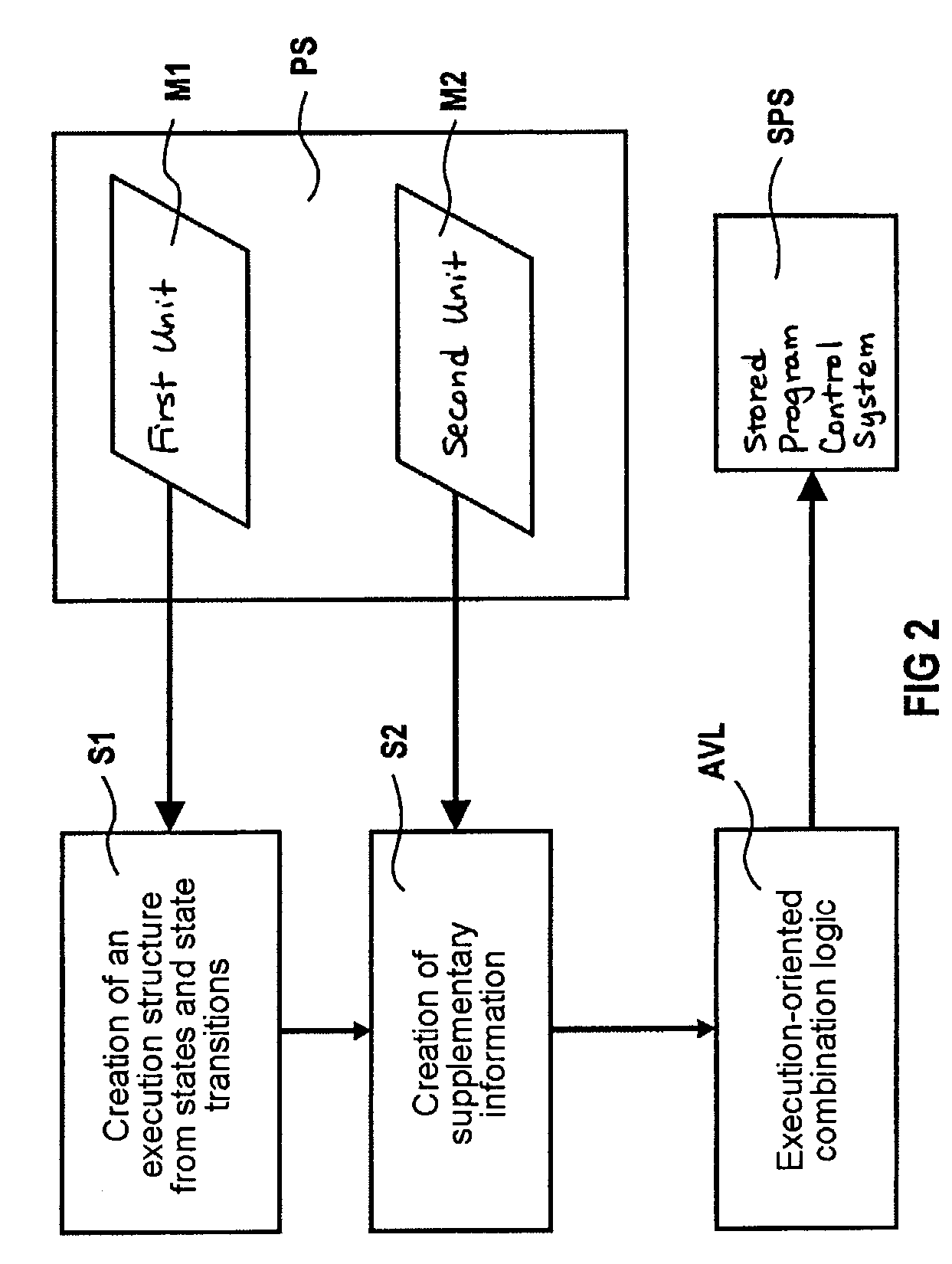
  • Application Information

AI Technical Summary

Benefits of technology

[0004]One aspect of the invention is based on the object of permitting low-cost programming of the automation system accompanied by a high level of data consistency.
[0005]One aspect of the invention is based on the recognition that the previous programming techniques used in the field of automation equipment, for example execution-oriented programming or combination-logic-oriented programming frequently have problems with respect to data consistency. Such inadequate data consistency results in particular from the fact that data which is created, for example, by a planner of an automation solution is repeatedly converted into different representations and documentations by the programmer of the automation solution and / or the tester of the automation solution. Generally, different documents are produced which in each case do not have any connection to one another at all. Such inadequate data consistency is avoided in that the data program which contains the automation solution is embodied as an execution-oriented combination logic. The execution-oriented combination logic is composed here, on the one hand, of an execution plan with the respective processing engineering sequence, the execution plan and the sequences present in it providing, in terms of programming, a combination logic which is necessary in each case. In this way, it is possible to both document and program an entire automation solution by creating a single document in the form of the execution-oriented combination logic. Overall, this thus results in the representation of execution controls and the computer-internal processing logic of combination logic control systems being combined and designing, programming and documentation of combination logic control systems taking place here in one working step and on the basis of a single data store, such that overall low-cost programming of an automation system accompanied by a maximum level of data consistency is obtained.
[0006]A high level of efficiency is achieved by virtue of the fact that the execution-oriented combination logic of the data program is provided for designing, programming and / or documentation.
[0009]In one advantageous refinement, the logic operations which can be edited by the magnifying glass function are implemented in a combination logic language and / or in an execution-oriented combination logic language. As a result, it becomes possible to integrate, even without previous knowledge, basic languages which have been used hitherto, such as Kontaktplan KOP, Funktionsliste FUP, Anweisungsliste AWL and others, into the system without effort.
[0010]A simple way of implementing the system is obtained by virtue of the fact that the system has a first unit for generating an execution structure from states and state transitions, at least for process engineering subsequences of the automation system, and a second unit for generating supplementary information which can be assigned to the states and / or the state transitions. This results in a data program with an execution logic which can be represented clearly, for the automation system.

Problems solved by technology

Such inadequate data consistency results in particular from the fact that data which is created, for example, by a planner of an automation solution is repeatedly converted into different representations and documentations by the programmer of the automation solution and / or the tester of the automation solution.

Method used


Image

  • System and method for programming and/or operating an automation system with execution-oriented combination logic
  • System and method for programming and/or operating an automation system with execution-oriented combination logic
  • System and method for programming and/or operating an automation system with execution-oriented combination logic

Examples


Embodiment Construction

[0023]Reference will now be made in detail to the preferred embodiments of the present invention, examples of which are illustrated in the accompanying drawings, wherein like reference numerals refer to like elements throughout.

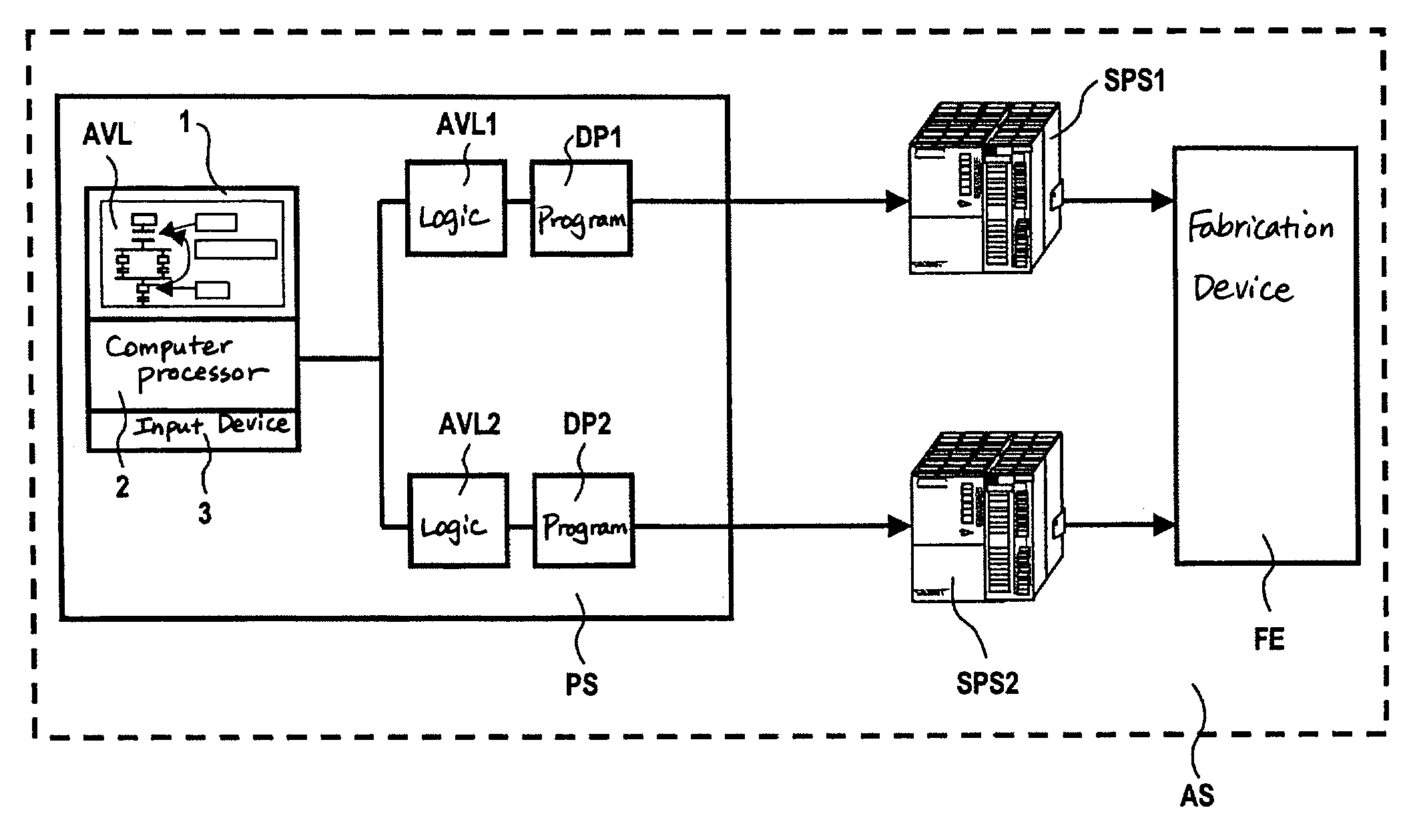
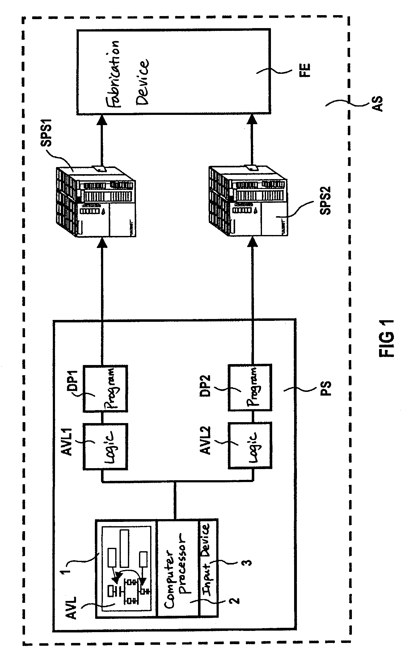
[0024]FIG. 1 shows a basic view of a block circuit diagram of the programming of an automation system AS. The automation system AS is composed of a programming system PS, of a first stored-program control system SPS1, of a second stored-program control system SPS2 and of a fabrication device FE. The programming system PS is used to create a first data program DP1, which can be executed on the first stored-program control system SPS1, and to program a second data program DP2, which can be executed on the second stored-program control system SPS2. The programming of the first and second data programs DP1, DP2 is carried out using a computer 1, 2, 3 which is formed from a computer 2, an associated keyboard 3 and an associated screen 1. On the screen 1 of the com...


PUM


Abstract

A system and a method for programming and / or operating an automation system has a programming system / method which presents the technological sequence as a chain of steps (or flowchart) but functions as a combination logic. For low-cost programming of the automation system accompanied by a high level of data consistency, it is proposed that, in order to program the automation system, a data program DP which can be executed on a data processing device and is formed, at the time of the execution, directly from a specific execution plan which contains the sequences of the program to be carried out as well as combination logic assigned to the sequences is provided. This results in an execution-oriented combination logic which can be used for designing, programming and / or documenting the data program of the automation system. The sequences and the combination logic assigned to the sequences are based here on a single data store so that when there are program changes no data inconsistencies whatsoever are produced, in contrast to previous solutions with different databases for designing, programming and / or documentation.

Description

CROSS REFERENCE TO RELATED APPLICATIONS[0001]This application is based on and hereby claims priority to German Application No. 102 15 196.2 filed on Apr. 5, 2002, the contents of which are hereby incorporated by reference.BACKGROUND OF THE INVENTION[0002]The invention relates to a system and method for programming automation systems and a computer program product for carrying out such a method.[0003]Such a system is used in particular in the field of automation equipment. In order to create, process, analyze and display such an automation program, programming tools are used which can be executed on a data processing device and which are capable of graphically displaying the automation program or a part of an automation program. For this purpose, various methods of representation for the automation program are possible, for example structograms, automatic state machines, circuit diagrams, functional diagrams etc. Many automation programs are capable of being represented in different ...

Claims


Application Information

Patent Timeline
Patent Type & Authority Patents(United States)
IPC IPC(8): G06F19/00G05B19/05
CPCG05B19/056G05B2219/13044G05B2219/13052G05B2219/13113G05B2219/13134Y02P90/02
Inventor HERKERT, GEBHARD
Owner SIEMENS AG
Learn More