
Systems and Methods for Offshore Power Generation Using Airborne Power Generating Craft Tethered to a Floating Structure

Inactive Publication Date: 2017-12-21
HART CHRISTOPHER G +3
View PDF29 Cites 13 Cited by
  • Summary
  • Abstract
  • Description
  • Claims
  • Application Information

AI Technical Summary

Benefits of technology

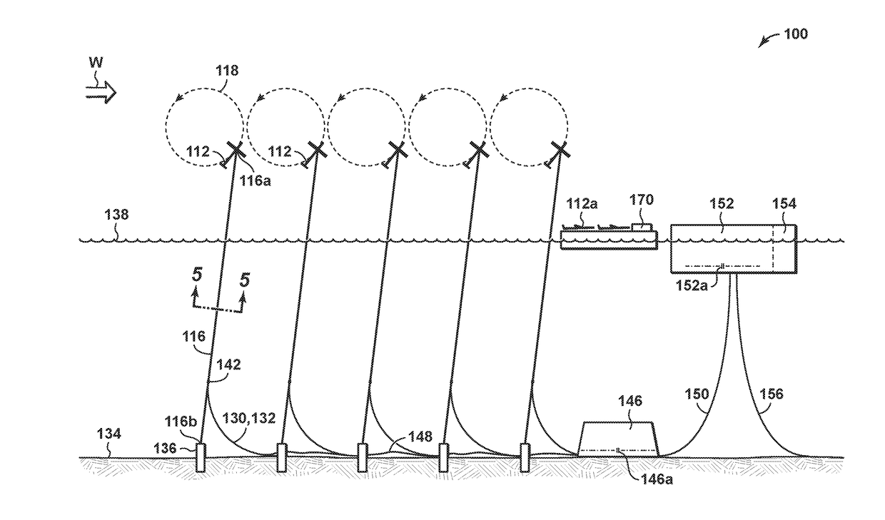
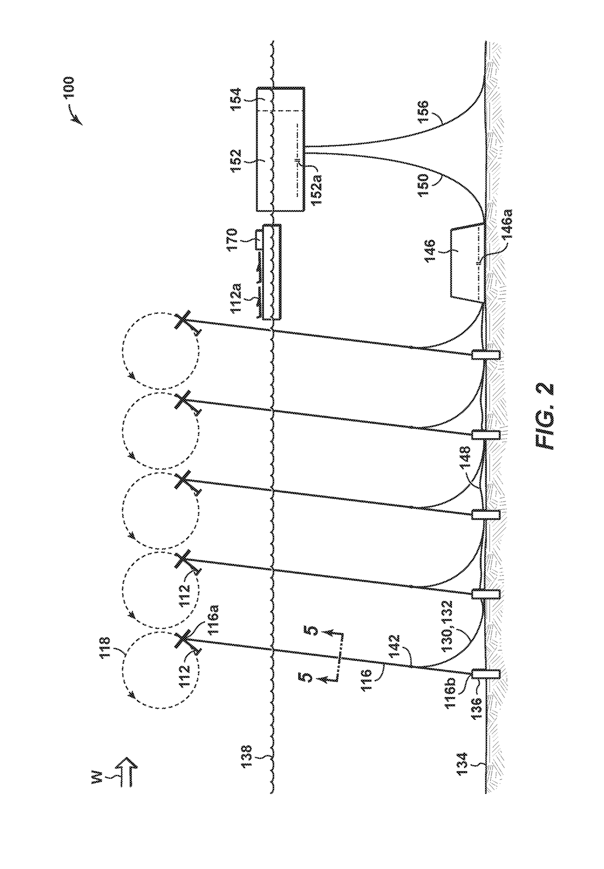
The present disclosure provides an offshore power generation system using an airborne power generating craft. The system includes a tether line connected between the airborne craft and a floating structure, which is connected to an anchor secured to the underwater floor. The tether line also connects to an electrical transmission system, which transmits power generated by the airborne craft. The system can also be designed to move in response to wind force, and the generated power can be used to power electrical devices on the ocean floor. Overall, the invention allows for efficient and effective offshore power generation using a tether line system.

Problems solved by technology

Accordingly, such concepts typically require large cranes for erection of the towers and turbines and are not optimal for wind turbines because of the large aerodynamic force in the direction of the wind as well as forces associated with dynamics from the angular momentum of the turbine blades.
Furthermore, wind and wave forces cause coupled motions of the support tower and the rotor blades, resulting in greater structural dynamic loads, deflections and stresses upon the wind turbine system.
The options of the prior art include large costly structures, with masses and / or dimensions often many times that of the wind turbine they are designed to support.
Such altitudes simply are not commercially accessible by conventional systems using a vertical support tower.
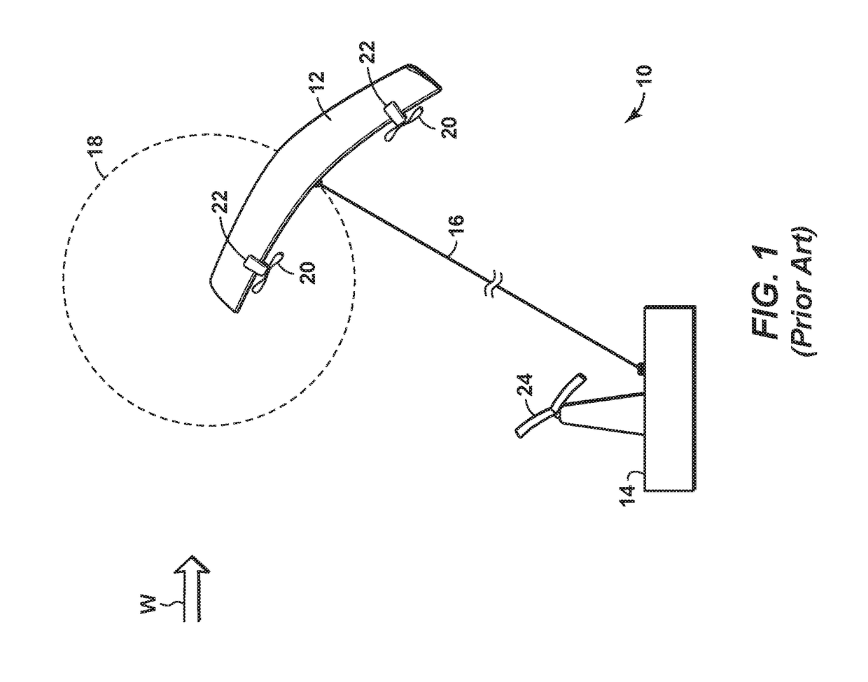
Such a solution still requires transporting and anchoring the semi-submersible structure, and these activities may reduce the commercial feasibility of system 10.

Method used


Image

  • Systems and Methods for Offshore Power Generation Using Airborne Power Generating Craft Tethered to a Floating Structure
  • Systems and Methods for Offshore Power Generation Using Airborne Power Generating Craft Tethered to a Floating Structure
  • Systems and Methods for Offshore Power Generation Using Airborne Power Generating Craft Tethered to a Floating Structure

Examples


Embodiment Construction

[0038]To promote an understanding of the principles of the disclosure, reference will now be made to the features illustrated in the drawings and specific language will be used to describe the same. It will nevertheless be understood that no limitation of the scope of the disclosure is thereby intended. Any alterations and further modifications, and any further applications of the principles of the disclosure as described herein are contemplated as would normally occur to one skilled in the art to which the disclosure relates. For the sake of clarity, some features not relevant to the present disclosure may not be shown in the drawings.

[0039]At the outset, for ease of reference, certain terms used in this application and their meanings as used in this context are set forth. To the extent a term used herein is not defined below, it should be given the broadest definition persons in the pertinent art have given that term as reflected in at least one printed publication or issued paten...


PUM


Abstract

A method of generating power. An airborne power generating craft is connected to a floating structure using an aloft portion of a tether line. The floating structure is connected to an anchor using an underwater portion of the tether line. The anchor is secured to an underwater floor. Power is generated based on movement of the airborne power generating craft in response to a wind force. The floating structure is connected to an electrical transmission system through at least part of the tether line. The generated power is transmitted to the electrical transmission system.

Description

CROSS-REFERENCE TO RELATED APPLICATIONS[0001]This application claims the priority benefit of U.S. Patent Application No. 62 / 351,541 filed Jun. 17, 2016 entitled SYSTEMS AND METHODS FOR OFFSHORE POWER GENERATION USING AIRBORNE POWER GENERATING CRAFT TETHERED TO A FLOATING STRUCTURE, the entirety of which is incorporated by reference herein.[0002]This application is related to U.S. Provisional Patent Application No. 62 / 351,528, entitled “Systems and Methods for Offshore Power Generation Using Airborne Power Generating Craft”; U.S. Provisional Patent Application No. 62 / 351,547, entitled “Methods and Systems of Maintaining an Offshore Power Plant”; U.S. Provisional Patent Application No. 62 / 351,550, entitled “Methods and Systems for Electrical Isolation in an Offshore Power Generation Plant” and U.S. Provisional Patent Application No. 62 / 351,552, entitled “Method and Systems for Maintaining an Offshore Power Plant Having Airborne Power Generating Craft”, all of which are filed on an eve...

Claims


Application Information

Patent Timeline
IPC IPC(8): F03D13/25F03D7/04H02G11/02B64C39/02B64F1/08F03D1/02
CPCF03D13/25F03D7/042H02G11/02F03D1/02F05B2240/90B64F1/08F05B2240/921F05B2240/92B64C39/022F03D5/00F05B2240/95Y02E10/70Y02E10/727Y02E10/72B64U10/60
Inventor HART, CHRISTOPHER G.BUSHBY, DONALD P.CASSIMERE, BRANDONLOKKEN, ROALD T.
Owner HART CHRISTOPHER G
Learn More