Method and apparatus for determining or predicting the position of a target

Active Publication Date: 2017-12-28
BRAINLAB
View PDF3 Cites 11 Cited by
  • Summary
  • Abstract
  • Description
  • Claims
  • Application Information

AI Technical Summary

Benefits of technology

The patent describes a method for accurately determining the position of a moving target using a single imaging device or multiple imagers. The method uses prior knowledge of the target's movement and a target movement model to determine the position of the target based on a single intersecting point. The decision of which intersecting point to use can be based on knowledge of the target's movement cycle. This method provides the advantage of being able to determine the target's position in more positions or states of the system. The target movement model can be determined and updated based on a number of points distributed over the target's movement. This method can be used in patient monitoring and radio therapy systems, providing more accurate target positioning.

Problems solved by technology

In particular, the acquiring step does not involve an invasive step which would represent a substantial physical interference with the body, requiring professional medical expertise to be carried out and entailing a substantial health risk even when carried out with the required professional care and expertise.
However, some of the changes in the anatomical structure, such as the pathological changes in the structures (tissue), may not be detectable and for example may not be visible in the images generated by the imaging methods.

Method used


Image

  • Method and apparatus for determining or predicting the position of a target
  • Method and apparatus for determining or predicting the position of a target
  • Method and apparatus for determining or predicting the position of a target

Examples


Embodiment Construction

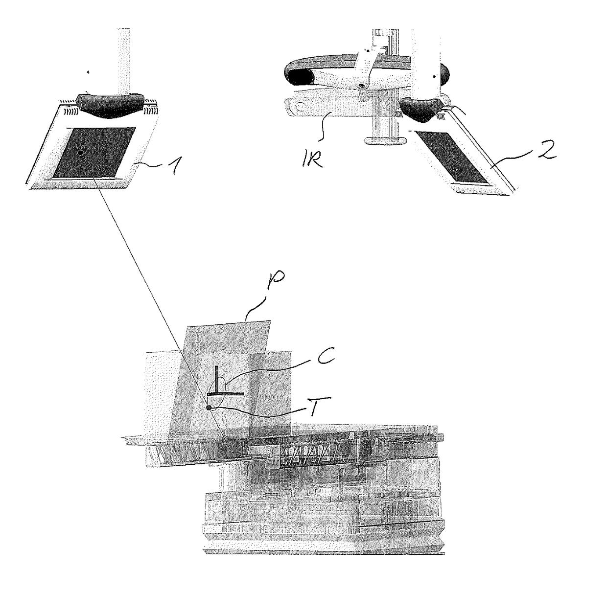
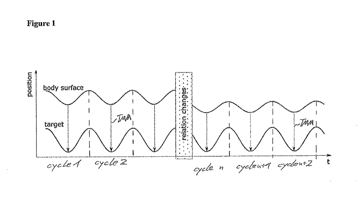
[0105]FIG. 1 shows in an abstract form a positional change of a surrogate signal being an upper sinusoidal wave. The surrogate signal might be the detected positions of one or more markers being located on the body surface of a patient, the body surface moving, for example due to a breathing motion. As can be seen on the left side of FIG. 1, the surrogate signal is a periodic signal having repeated cycles 1, 2, . . . .

[0106]Below the surrogate signal there is shown as another sinusoidal signal the position of a target also moving due to a vital motion, such as a breathing motion. Same as the above surrogate signal, the below target position performs a periodic movement.

[0107]If the target's position at a specific time is correlated with the marker position or surrogate signal, then a target-marker-model TMM or in an abstract manner a correlation model can be defined specifying the relation between the detected surrogate signal (e.g. movement of the body surface) with the movement of...


PUM


Abstract

A data processing method for determining the position of a target, comprising the steps performed by a computer: a) acquiring a target movement model specifying a movement cycle of the target; b) acquiring a target position signal representing a view of the target from a single direction and / or provided by a single imager; c) determining, based on the acquired target position signal and the target movement model, the position of the target.

Description

FIELD OF THE INVENTION[0001]The present invention is directed to the determination of the position or a positional information of a target, such as a structure moving within a body, which determined position can for example be used to control irradiation of the target. The determined position can be used to update a correlation model correlating a surrogate signal, such as an IR marker signal with the position of the target.BACKGROUND OF THE INVENTION[0002]During the performance of a dynamic tracking or gated patient treatment in the field of radio therapy, a surrogate signal, such as a breathing signal, used to determine or correlate and extrapolate the target motion internal of the patient may change as the patient rests on the couch. A change may result from a repeated vital motion, such as breathing or heartbeat, but may also change in a more permanent manner, i.e. the change is not a repeated movement. This later change is primarily manifested as a shift called baseline shift. ...

Claims


Application Information

Patent Timeline
IPC IPC(8): A61N5/10A61B6/02G06T7/73G06T7/246
CPCA61N5/1049A61B6/022G06T7/251G06T7/75A61N2005/1061G06T2207/10116G06T2207/30204G06T2207/10012G06T2207/10048A61B6/12A61B6/5264G06T7/246G06T2207/30004
Inventor HEINRICH, STEFFENBERLINGER, KAJETANMARIC, MILOSSPIKA, CHRISTIAN
Owner BRAINLAB
Why Eureka
Try Eureka