Tool holder

a tool and tool holder technology, applied in the field of tool holders, can solve the problems of cooling fluid to be affected, and achieve the effects of preventing the leakage of coolant, facilitating the separation of the coolant ejection member, and efficient supply of coolan

Active Publication Date: 2017-12-28
MITSUBISHI MATERIALS CORP
View PDF31 Cites 8 Cited by
  • Summary
  • Abstract
  • Description
  • Claims
  • Application Information

AI Technical Summary

Benefits of technology

[0028]Furthermore, since the contact resistance between the tubular portion and the hole portion or the like of the tool body in which the tubular portion is disposed is increased by the seal member, the easy separation of the coolant ejection member from the tool body, which is caused by coolant supply pressure or the like, is suppressed. That is, an action for retaining the coolant ejection member can be obtained by the seal member.
[0029]Moreover, in the tool holder of the invention, it is preferable that a housing recess, which communicates with the coolant supply passage, is formed at the leading end portion of the tool body and the coolant ejection member is housed in the housing recess.
[0030]In this case, since the coolant ejection member is housed in the housing recess, the significant projection (protrusion) of the tool body from the leading end portion is suppressed.
[0031]Accordingly, while the above-mentioned significant functional effects are obtained by the coolant ejection member, the tool holder can be made compact and a situation in which the conditions of turning are limited since the coolant ejection member is mounted can also be prevented.
[0032]According to the tool holder of the invention, it is possible to efficiently supply a coolant to a flank and a cutting edge by preventing the leakage of a coolant and to accurately and stably supply a coolant so as to correspond to the shapes of various cutting edges or the types of cutting.

Problems solved by technology

According to this structure, since it is difficult for a coolant to be affected by swarf in comparison with other structures that supply a coolant to the cutting edge from the face even though a coolant is supplied from outside or inside, the coolant easily reaches the cutting edge.

Method used


Image

  • Tool holder
  • Tool holder
  • Tool holder

Examples


first embodiment

[0057]A tool holder 30, which is a tool holder according to a first embodiment of the invention, will be described below with reference to the drawings.

[0058]The tool holder 30 of this embodiment is to perform turning (cutting) on a work material that is made of a metal material or the like.

[Schematic Structure of Tool Holder]

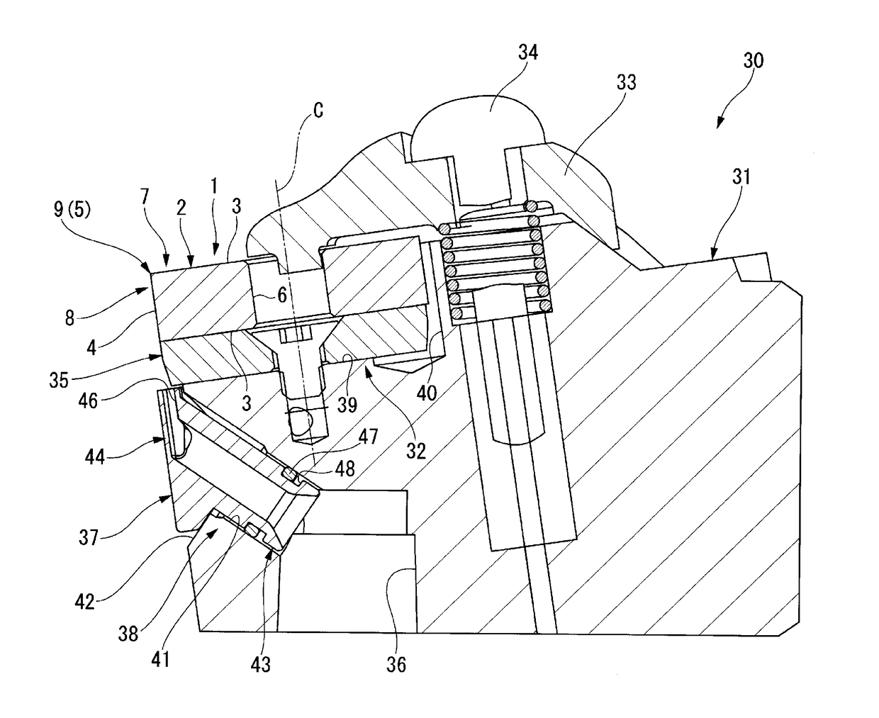
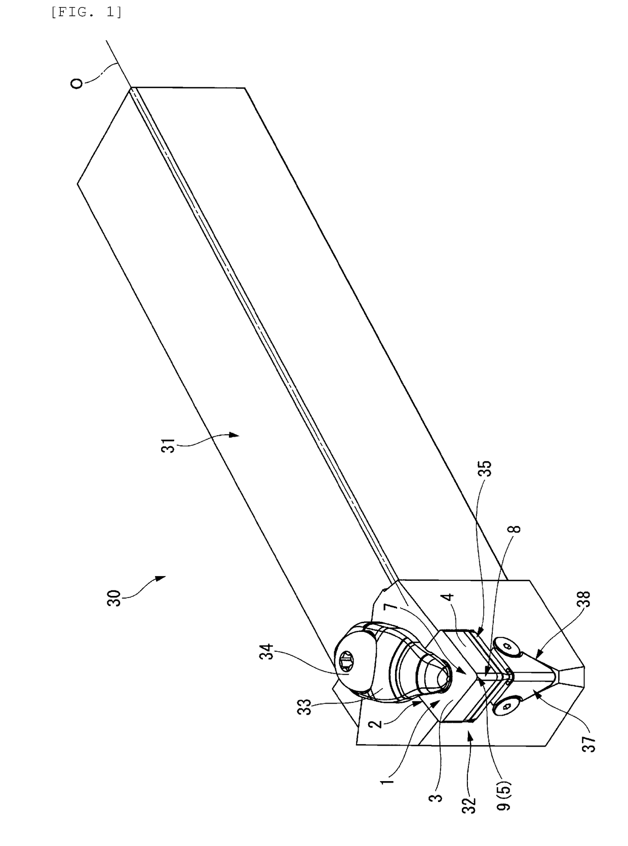
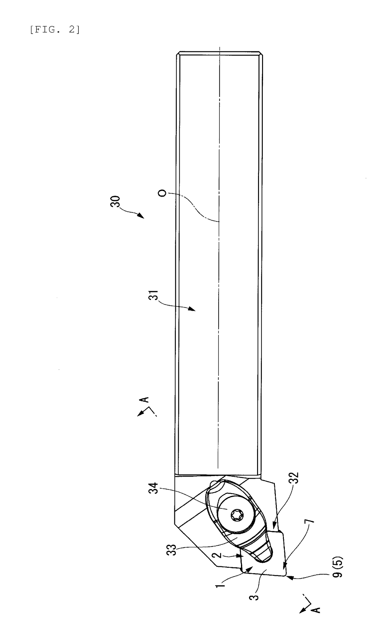
[0059]As illustrated in FIGS. 1 to 6, the tool holder 30 includes a cutting insert 1 that is made of a hard material, such as cemented carbide, and a tool body 31 which is made of a steel material or the like and on which the cutting insert 1 is detachably mounted.

[0060]The tool body 31 has the shape of a shaft, and the cutting insert 1 has the shape of a plate and is disposed at the leading end portion of the tool body 31. Further, a face 7, a flank 8, and a cutting edge 5 that forms an intersection ridge between the face 7 and the flank 8 are formed on the cutting insert 1.

[0061]Although not particularly shown, a work material, which is to be subjected to tur...

second embodiment

[0150]Next, a tool holder 60 according to a second embodiment of the invention will be described with reference to FIGS. 22 to 25.

[0151]The detailed description of the same components as the components of the above-mentioned embodiment (first embodiment) will be omitted and only differences between the components of the second embodiment and the components of the first embodiment will be described below.

[0152]As shown in FIG. 22, the tool holder 60 of the second embodiment uses a coolant ejection member 61, at which the notch recesses 49 are not formed, instead of the coolant ejection member 37 described in the first embodiment. Further, the tool holder 60 does not include the mounting screws 45.

[0153]The tool holder 60 of this embodiment has a separation regulating structure (retaining structure) that can prevent the separation of the coolant ejection member 61 from the housing recess 38 without using the mounting screws 45.

[Separation Regulating Structure]

[0154]The separation regu...


PUM


Abstract

An object is to provide a tool holder that can efficiently supply a coolant to a flank and a cutting edge by preventing the leakage of a coolant and can accurately and stably supply a coolant so as to correspond to the shapes of various cutting edges or the types of cutting. A face, a flank, and a cutting edge forming an intersection ridge between the face and the flank are disposed at a leading end portion of a shaft-shaped tool body in a tool holder. A coolant supply passage is formed in the tool body, and a coolant ejection member is detachably provided at the leading end portion of the tool body. The coolant ejection member includes a tubular portion, and an ejection hole that communicates with the coolant supply passage through the inside of the tubular portion and opens toward the flank and the cutting edge.

Description

TECHNICAL FIELD[0001]The present invention relates to a tool holder having a structure that supplies a coolant to a flank and a cutting edge.BACKGROUND ART[0002]A tool holder disclosed in, for example, PTL 1 is known as a tool holder in the related art. In the tool holder, a plate-like cutting insert is detachably disposed at the leading end portion of a shaft-shaped tool body, and the cutting insert includes a face, a flank, and a cutting edge that forms an intersection ridge between the face and the flank.[0003]Further, an oil hole (coolant supply passage) in which a coolant (oil-based or water-soluble cutting fluid) flows is formed in the tool body, and a plate-like member including a recess is mounted on the leading end portion of the tool body. Furthermore, a coolant is ejected to the flank and the cutting edge from the oil hole through the recess of the plate-like member in a direction parallel to the flank of the cutting insert. This method of ejecting a coolant is referred t...

Claims


Application Information

Patent Timeline
Patent Type & Authority Applications(United States)
IPC IPC(8): B23B27/10B23Q11/10
CPCB23B27/10B23B2250/12B23Q11/10
Inventor IMAI, YASUHARUTAKAHASHI, HIDEBUMI
Owner MITSUBISHI MATERIALS CORP
Why Eureka
Try Eureka