System and method for improving the liquefaction rate in cryocooler-based cryogen gas liquifiers

Inactive Publication Date: 2017-12-28
UNIV DE ZARAGOZA +1
View PDF6 Cites 0 Cited by
  • Summary
  • Abstract
  • Description
  • Claims
  • Application Information

AI Technical Summary

Benefits of technology

The present invention provides a gas liquefaction system and method based on cryocoolers that makes better use of the cooling power from the cryocooler to improve liquefaction. It takes advantage of the already cooled gas inside the cryocooler to extract small volumes of gas from the coldest part of the cryocooler and add it to the liquefaction region of the storage container, thereby increasing the liquefaction rate while keeping the pressure inside the container constant. The system achieves higher efficiencies and stability by extracting small volumes of gas and controlling the pressure of the gas and condensing gas in the liquefaction region.

Problems solved by technology

Currently available small-scale liquefaction plants for producing less than 100 liters of liquefied cryogen per day, or “Class S” liquefiers, are substantially inefficient when compared to performances obtained by larger scale liquefaction plants.
In addition, the medium and large-scale plants involve substantial complexity, require extensive maintenance and their liquefaction rates, >15 liters / hour (i.e. >360 liters / day)), are far in excess of the needs of many users.

Method used


Image

  • System and method for improving the liquefaction rate in cryocooler-based cryogen gas liquifiers
  • System and method for improving the liquefaction rate in cryocooler-based cryogen gas liquifiers
  • System and method for improving the liquefaction rate in cryocooler-based cryogen gas liquifiers

Examples


Embodiment Construction

[0058]In the following description, for purposes of explanation and not limitation, details are set forth in order to provide a thorough understanding of the present invention. However, it will be apparent to those skilled in the art that the present invention may be practiced in other embodiments that depart from these details and descriptions without departing from the spirit and scope of the invention. Certain embodiments will be described below with reference to the drawings wherein illustrative features are denoted by reference numerals.

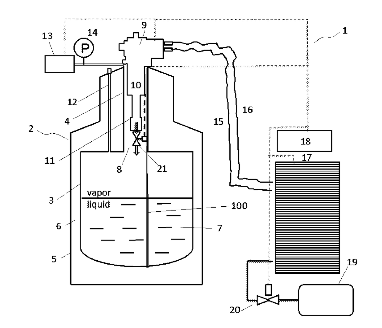
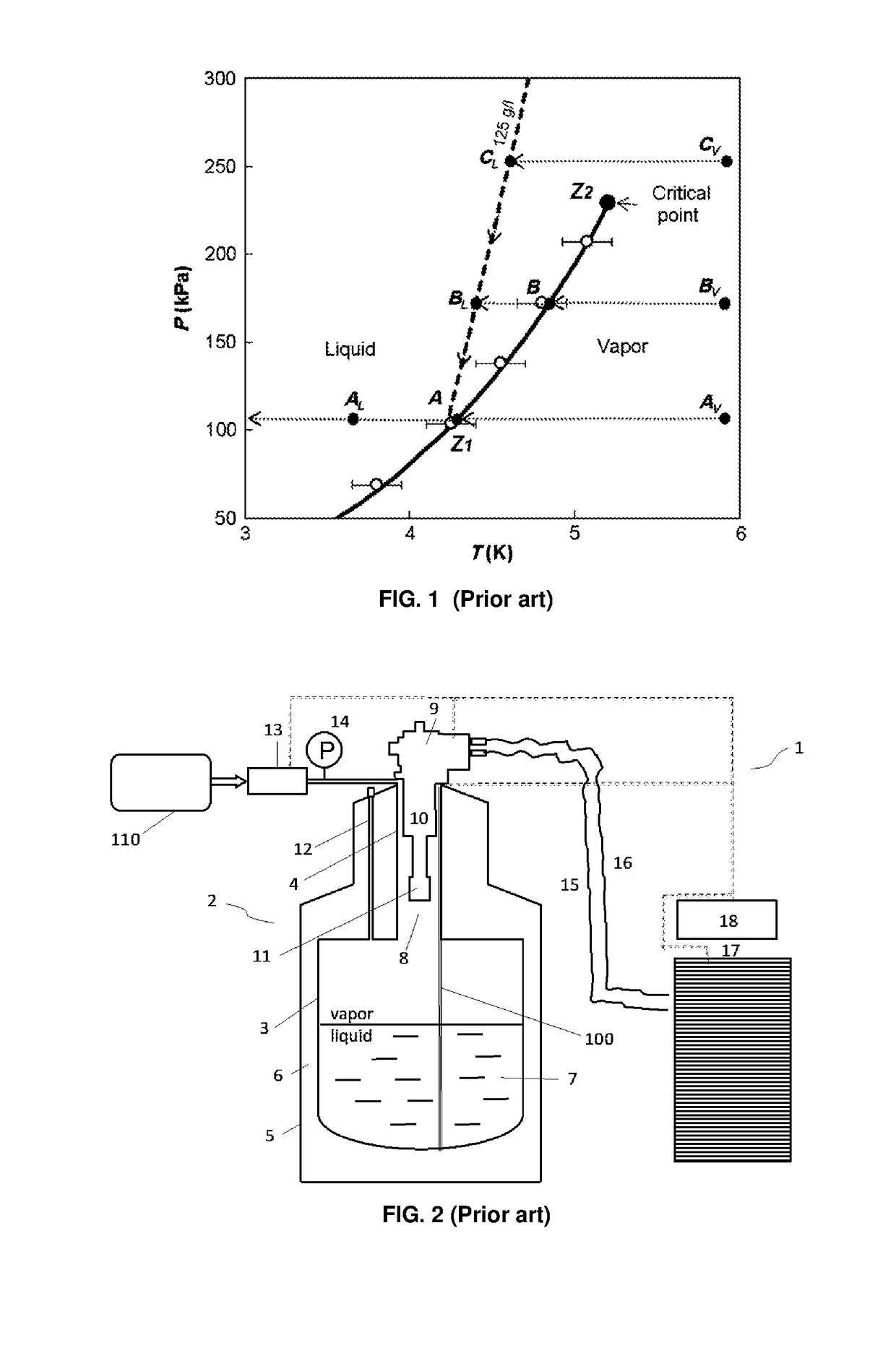
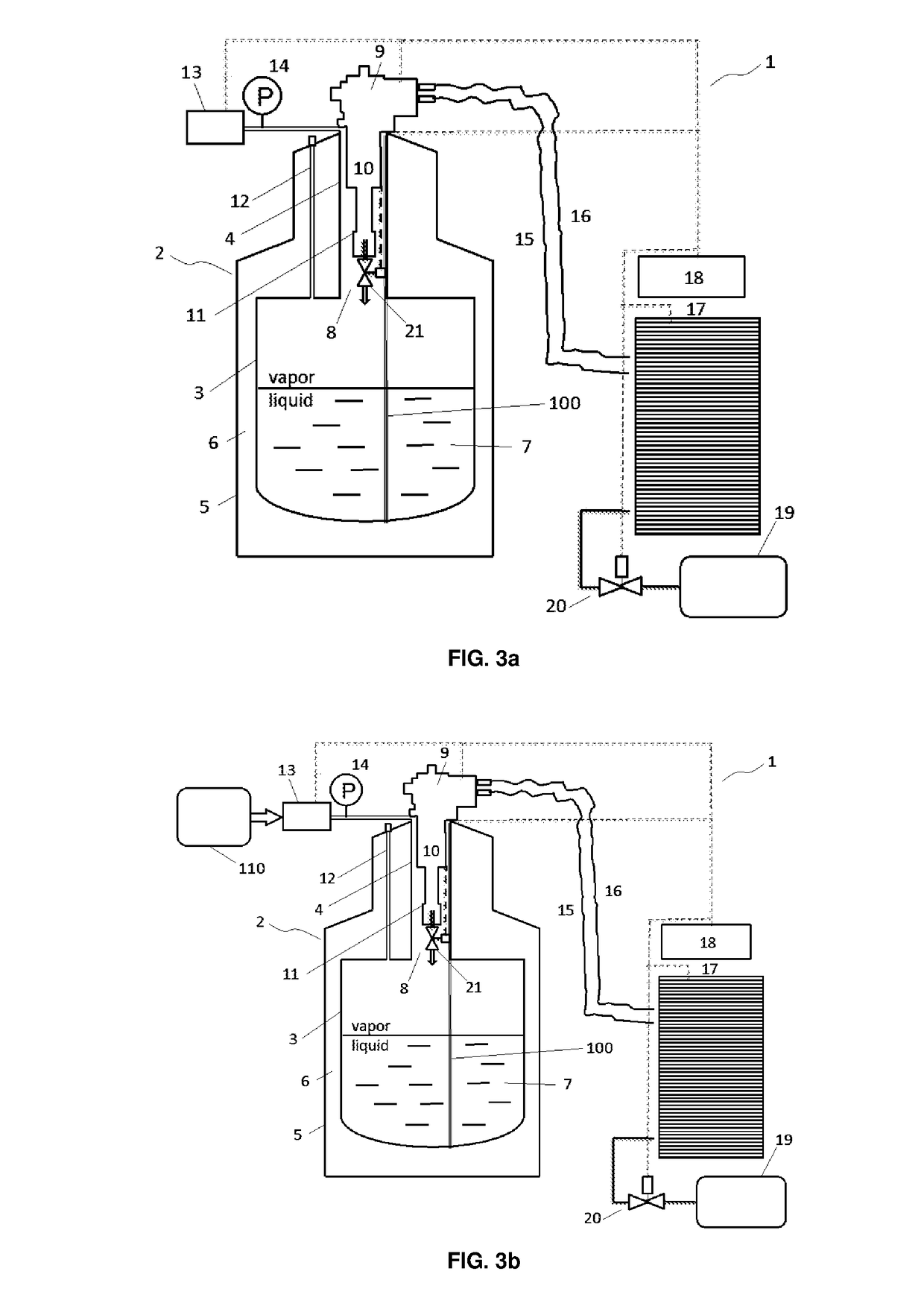
[0059]In a general embodiment according to FIG. 2, a known liquefaction system (1), also referred to herein as a cryostat, includes an isolated storage container (2) or Dewar comprising a liquid storage portion (3) and a neck portion (4) extending therefrom, and connected to an outer vessel (5) which is at ambient temperature. The storage container (2) is insulated by a shell (6) with the volume within the shell (6) external of the storage porti...


PUM


Abstract

The present invention relates to a cryogen-gas liquefaction system (1) and method comprising: a storage container (2) comprising a liquid storage portion (3) and a neck portion (4) with a liquefaction region (8) above said bath (7); a coldhead (9) arranged at the neck portion (4) comprising one or more refrigeration stages (10, 11); a gas intake module (12) containing an amount of gas-phase cryogen for its introduction into the storage container (2); and a pressure control mechanism (13) for controlling the cryogen gas pressure within the liquefaction region (8) of the storage container (2). Advantageously, the coldhead (9) further comprises: a refrigeration compressor (17) for distributing gas-phase cryogen inside the coldhead (9); one or more extraction orifices (22) communicating a gas circulation circuit inside the coldhead (9) with the external region of the refrigeration stages (10, 11), acting as pass-through ports (23); and a gas injection source (19) connected with the gas circulation circuit of said refrigeration compressor (17) through a gas injection valve (20), that maintains a total amount of gas constant in the compressor gas circuit, to compensate for the amount of gas extracted and liquefied through the extraction orifices (22).

Description

CROSS-REFERENCE TO RELATED APPLICATIONS[0001]The present application claims priority to European Patent Application No. 16382300.8 filed on Jun. 24, 2016, the disclosure of which is incorporated herein by reference.STATEMENT RE: FEDERALLY SPONSORED RESEARCH / DEVELOPMENT[0002]Not ApplicableBACKGROUND OF THE INVENTION1. Field of the Invention[0003]The present invention relates generally to systems and methods for liquefaction of gases, and more particularly to such systems and methods adapted for obtaining improved liquefaction and performance efficiency. The main field of application of the invention is helium liquefaction technologies such as small-scale liquefiers of <100 liter / day liquefaction rates, based on closed-cycle cryocoolers.2. Description of the Related Art[0004]Helium is a scarce element on earth and its numerous scientific and industrial applications continue to drive a growing demand. For example, common uses of gas-phase helium include welding, lifting (balloons), ...

Claims


Application Information

Patent Timeline
IPC IPC(8): F25J1/00G05D16/20F25B9/12F25J1/02
CPCF25J1/0007G05D16/206F25J1/0225F25J2270/908F25J1/0276F25J2270/912F25B9/12F25J1/0202F25B9/002F25B9/10F25B19/005
Inventor MILLAN, CONRADO RILLOMONCLUS, JAVIER SESE
Owner UNIV DE ZARAGOZA
Why Eureka
Try Eureka