
Method and apparatus for calibrating a rotating device attached to a movable part of a coordinate measuring device

Active Publication Date: 2017-12-28
CARL ZEISS IND MESSTECHN GMBH
View PDF2 Cites 12 Cited by
  • Summary
  • Abstract
  • Description
  • Claims
  • Application Information

AI Technical Summary

Benefits of technology

The position determining device described in this patent allows for accurate positioning of a body, such as a sphere or spherical cap, by using multiple sensors to measure the relative position with respect to different degrees of movement. The device can measure contactlessly, without causing any force or hysteresis effects, and friction between the sensors and the rotary apparatus or body connected thereto can be avoided. This makes the method faster and more accurate for calibration compared to classical methods. The device can determine the relative position with respect to two or three linear degrees of movement, and can be particularly useful for determining the position of a spherical body during tool center point movement.

Problems solved by technology

Changes in geometry (that is to say changes in shape and / or dimensions) over the course of time can be attributed to changes in temperature and to wear.
In general, the rotary movements about the respective axis of rotation are not ideal rotary movements.
The long duration gives rise to additional inaccuracies of the calibration if the boundary conditions (in particular the temperature distribution) change during the calibration.

Method used


Image

  • Method and apparatus for calibrating a rotating device attached to a movable part of a coordinate measuring device
  • Method and apparatus for calibrating a rotating device attached to a movable part of a coordinate measuring device
  • Method and apparatus for calibrating a rotating device attached to a movable part of a coordinate measuring device

Examples


Embodiment Construction

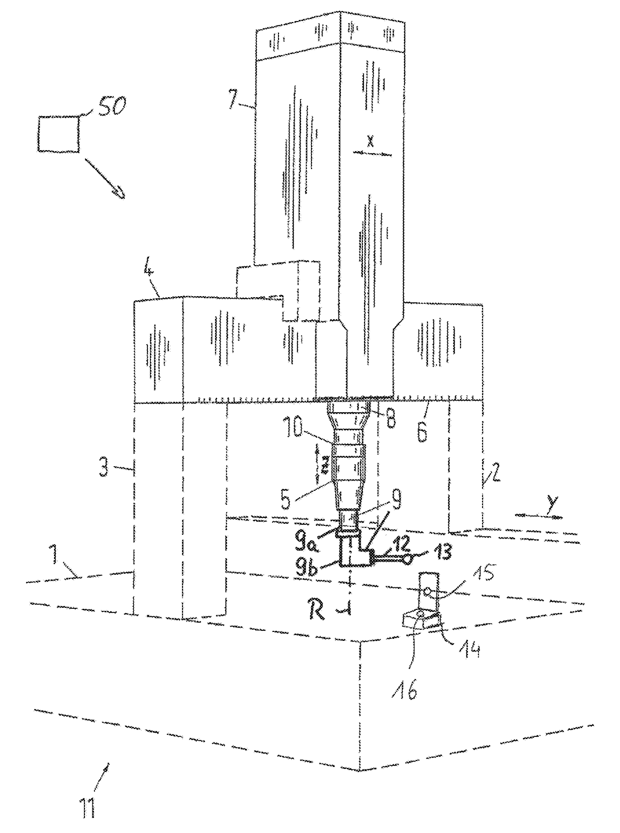
[0075]The coordinate measuring machine (CMM) 11 with a portal design, depicted in FIG. 1, comprises a base 1 designed as a measurement table, above which columns 2, 3 are arranged in a manner movable in the Y direction of a Cartesian coordinate system with the coordinate axes X-Y-Z. Together with a crossbeam 4, the columns 2, 3 form a portal of the CMM 11. At its opposite ends, the crossbeam 4 is connected to the columns 2 and 3, respectively. Electric motors not depicted in any more detail cause the linear movement of the columns 2, 3 in the Y direction. Here, for example, one electric motor is associated with each one of the two columns 2, 3.

[0076]The crossbeam 4 is combined with a cross slide 7, which is movable, by way of air bearings, along the crossbeam 4 in the X direction of the Cartesian coordinate system. The current position of the cross slide 7 relative to the crossbeam 4 can be determined on the basis of a scale graduation 6. The movement of the crossbeam 4 in the X dir...


PUM


Abstract

A method for calibrating a rotating device attached to a movable part of a coordinate measuring device having a first part secured to the movable part and a second part rotatable relative to the first part about an axis of rotation of the turning device, on which second part a measuring sensor for measuring workpieces can be attached. The rotating device or a body connected to the second part is moved to a local area of a position determining device by a drive system of the coordinate measuring device, which position measuring device is connected to the coordinate measuring device, by means of at least one sensor of the position determining device. A position of the rotating device or of the body connected to the second part is determined relative to the position determining device, and the rotating device is calibrated in accordance with the determined position.

Description

CROSS-REFERENCE OF RELATED APPLICATIONS[0001]This application is a continuation application of International patent application PCT / EP2016 / 056164, filed Mar. 21, 2016, which claims the priority of German patent application DE 10 2015 205 567.1, filed Mar. 26, 2015. The entire contents of these priority applications are incorporated herein by reference.BACKGROUND OF THE INVENTION[0002]The invention relates to a method and an arrangement for calibrating a rotary apparatus mounted on a movable part of a coordinate measuring machine.[0003]It is known to use coordinate measuring machines (abbreviated to CMM) to determine coordinates of workpieces. Here, in some cases, a rotary apparatus is used which can bring the sensor, which is mounted on the movable part of the CMM, into different rotary positions. The sensor, which is in turn mounted on the rotary apparatus, may for example be a tactile probe for probing the surface of workpieces, that is to say, upon contact with the surface, using...

Claims


Application Information

Patent Timeline
IPC IPC(8): G01B5/012
CPCG01B5/012G01B21/042
Inventor HELD, TOBIASSAGEMUELLER, RAINERSEITZ, DOMINIK
Owner CARL ZEISS IND MESSTECHN GMBH
Features
  • Generate Ideas
  • Intellectual Property
  • Life Sciences
  • Materials
  • Tech Scout
  • Unparalleled Data Quality
  • Higher Quality Content
  • 60% Fewer Hallucinations
Learn More