Presenting objects in a sonar image of an underwater environment

Inactive Publication Date: 2017-12-28
NAVICO HLDG
View PDF22 Cites 17 Cited by
  • Summary
  • Abstract
  • Description
  • Claims
  • Application Information

AI Technical Summary

Benefits of technology

[0014]In some embodiments, the method further comprises determining the one or more groups of sonar returns associated with the one or more objects in the underwater environment further by determining a material of an object causing the sonar returns of each cluster based on power and gain of the at least one transducer element, density of the sonar returns within the cluster, and the strength value of at least one of the sonar returns within the cluster.
[0015]In some embodiments, the method further comprises determining the one or more groups of sonar returns associated with the one or more objects in the underwater environment further by determining at least one of a shape, a size, and a direction of movement of an object associated with each cluster.
[0016]In some embodiments, the method further comprises determining the one or more groups of sonar returns associated with the one or more objects in the underwater environment further by generating a first 2D representation of each sonar return in at least one cluster, wherein the first 2D representation includes the x coordinate and the y coordinate of each sonar return in the at least one cluster; generating a second 2D representation of each sonar return in at least one cluster, wherein the second 2D representation includes the x coordinate and the z coordinate of each sonar return in the at least one cluster; generating a third 2D representation of each sonar return in at least one cluster, wherein the third 2D representation includes the y coordinate and the z coordinate of each sonar return in the at least one cluster; and analyzing the first 2D representation, the second 2D representation, and the third 2D representation to determine one or more characteristics of the at least one cluster. In some embodiments, the one or more characteristics of the at least one cluster include at least one of a shape, a size, and a direction of movement of an object associated with each cluster.
[0017]In some embodiments, the method further comprises analyzing the one or more groups of sonar returns associated with the one or more objects to determine movement of the one or more objects. Additionally, the method comprises generating the 3D image of the one or more sonar returns associated with the one or more objects by generating a trail that corresponds to the movement of the one or more objects.
[0018]In some embodiments, the method further comprises generating a second 3D matrix based on second sonar return data received from the underwater environment. Additionally, the method comprises determining one or more second groups of sonar returns among a plurality of sonar returns in the second 3D matrix associated with the one or more objects in the underwater environment. Additionally, the method comprises analyzing the one or more groups of sonar returns associated with the one or more objects and the one or more second groups of sonar returns associated with the one or more objects to determine movement of the one or more objects. Further, the method comprises generating the 3D image of the one or more sonar returns associated with the one or more objects by generating a trail that corresponds to the movement of the one or more objects.
[0019]In some embodiments, the method further comprises generating the 3D image of the one or more groups of sonar returns associated with the one or more objects by generating one or more mesh images characterizing the respective one or more objects based on the sonar returns associated with the corresponding object.

Problems solved by technology

Applicant has further identified a number of deficiencies and problems associated with conventional sonar systems and other associated systems.

Method used


Image

  • Presenting objects in a sonar image of an underwater environment
  • Presenting objects in a sonar image of an underwater environment
  • Presenting objects in a sonar image of an underwater environment

Examples


example sonar

Overview of Example Sonar and Transducer Elements

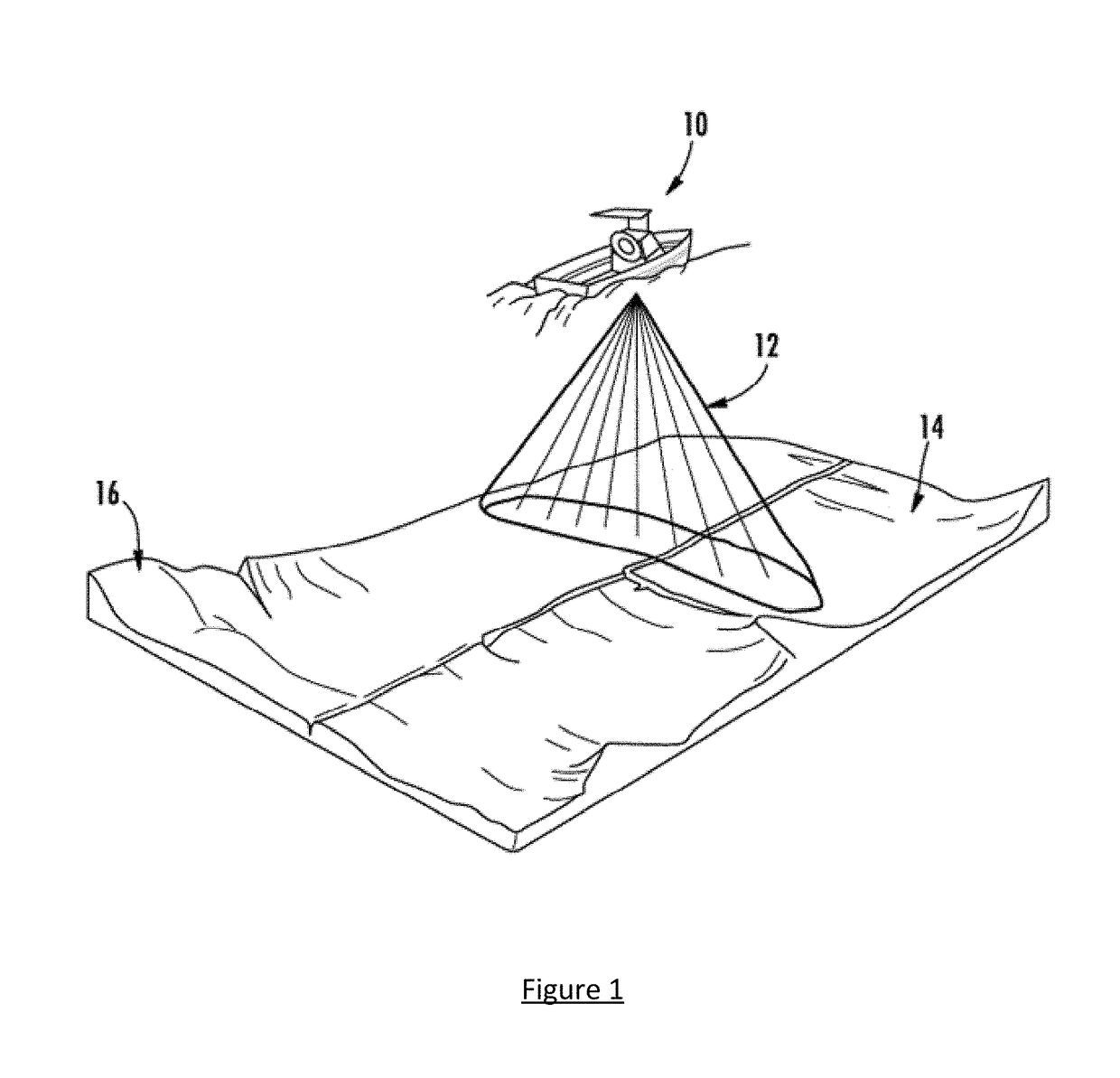
[0045]Sonar systems, such as sonar depth finders, sidescan sonars, downscan sonars, and sonar fish finders, are commonly employed by boaters, sport fishermen, search and rescue personnel, researchers, surveyors, and others. With reference to FIG. 1, a boat 10 may include a sonar system configured to create electrical pulses from a transceiver. A transducer then converts the electrical pulse into sound waves 12, which are sent into the water. In the depicted embodiment, a fan-shaped sound beam (e.g., a beam shape created from one or more linear transducers) is being transmitted into the water, however, as will be apparent to one of ordinary skill in the art in view of this disclosure, other sound beam configurations (e.g., conical shaped, elliptical shaped, multiple conical shaped, etc.) may be transmitted.

[0046]When the sound waves 12 strike anything of differing acoustic impedance (e.g., the sea floor or something suspended in the wa...


PUM


Abstract

A sonar system is provided including a display screen, a transducer assembly including at least one transducer that is configured to emit one or more sonar signals into an underwater environment and receive sonar return data reflected from one or more objects, and a sonar module configured to generate a 3D matrix based on the sonar return data including a plurality of sonar returns that are each defined by a 3D positional value, determine a group of the plurality of sonar returns associated with an object, assign a predetermined icon to the determined group, and generate and display 3D image of the sonar return data. The predetermined icon is positioned within the 3D image at a position that corresponds to the position of the determined group such that the position of the predetermined icon corresponds to the position of the object.

Description

CROSS-REFERENCE TO RELATED APPLICATION[0001]This application is a continuation-in-part of application Ser. No. 15 / 098,603, filed Apr. 14, 2016, and entitled “Methods and Apparatuses for Constructing a 3D Sonar Image of Objects in an Underwater Environment,” which claims priority to U.S. Provisional Patent Application No. 62 / 149,789, filed Apr. 20, 2015, and entitled “Method and Apparatuses for Constructing a 3D Sonar Image of Objects in an Underwater Environment,” the contents of each being incorporated by reference herein in their entirety.TECHNICAL FIELD[0002]Example embodiments of the present invention relate generally to sonar systems and, more particularly, to methods and apparatuses for processing sonar returns to produce a three-dimensional (3D) image of objects in an underwater environment.BACKGROUND[0003]Sonar (SOund Navigation And Ranging) has long been used to detect waterborne or underwater objects. For example, sonar devices may be used to determine depth and bottom top...

Claims


Application Information

Patent Timeline
Patent Type & Authority Applications(United States)
IPC IPC(8): G01S15/89G01S7/539G01S7/62G01S15/96
CPCG01S15/8902G01S7/539G01S7/6245G01S15/96G01S7/6272G01S15/87G01S15/89
Inventor CLARK, JEREMIAH D.HUNT, MATTHEWKIRMANI, SHAHZAD F.
Owner NAVICO HLDG
Why Eureka
Try Eureka