Illumination systems and devices for fourier ptychographic imaging

Active Publication Date: 2017-12-28
CANON KK
View PDF16 Cites 30 Cited by
  • Summary
  • Abstract
  • Description
  • Claims
  • Application Information

AI Technical Summary

Benefits of technology

[0032](d) a processor for computationally reconstructing a relatively higher-resolution image of the specimen by iteratively up

Problems solved by technology

Although the lower resolution images are real images, the higher resolution image is complex.
On the

Method used


Image

  • Illumination systems and devices for fourier ptychographic imaging
  • Illumination systems and devices for fourier ptychographic imaging
  • Illumination systems and devices for fourier ptychographic imaging

Examples


Embodiment Construction

Context

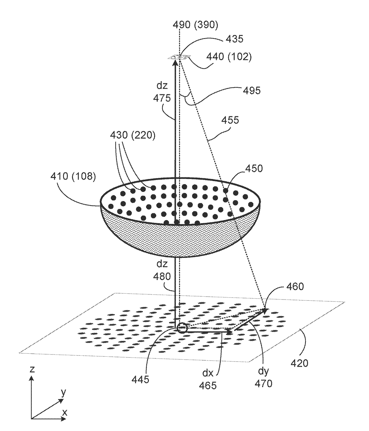
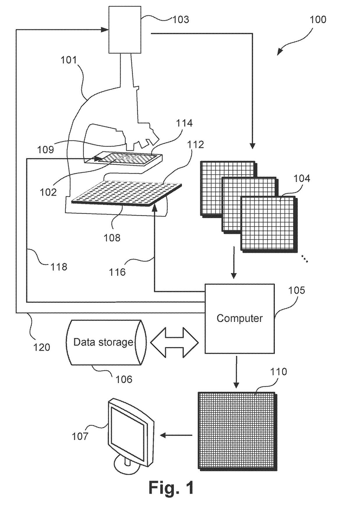
[0054]FIG. 1 shows a high-level system diagram for a microscope capture system 100 suitable for Fourier Ptychographic Microscopy (FPM). A specimen 102 is physically positioned on a stage 114 under an optical element, such as a lens 109, and within the field of view of a microscope 101. The microscope 102 in the illustrated implementation has a stage 114 that may be configured to move in order to correctly place the specimen in the field of view of the microscope at an appropriate depth. The stage 114 may also move as multiple images of the specimen 102 are captured by a camera 103 mounted to the microscope 101. In a standard configuration, the stage 114 may be fixed during image capture of the specimen.

[0055]A variable illumination system (illuminator) 108 is positioned in association with the microscope 101 so that the specimen 102 may be illuminated by coherent or partially coherent light incident at different angles. The illuminator 108 typically includes small light emitt...


PUM


Abstract

A system for forming an image (110) of a substantially translucent specimen (102) has an illuminator (108) configured to variably illuminate the specimen from a plurality of angles of illumination such that (a) when each angle (495) at a given point on the specimen is mapped to a point (445) on a plane (420) perpendicular to an optical axis (490), the points on the plane have an increasing density (e.g. FIGS. 4, 11C, 11E, 12C, 12E, 13A, 14A, 14C, 14E, 15A, 15C, 15E) towards an axial position on the plane; or (b) the illumination angles are arranged with a substantially regular pattern in a polar coordinate system (FIG. 13A,13B) defined by a radial coordinate that depends on the magnitude of the distance from an optical axis and an angular coordinate corresponding to the orientation of the angle relative to the optical axis. A detector is configured to acquire a plurality of variably illuminated, relatively lower-resolution intensity images (104) of the specimen based on light emitted from the illuminator according to variable illumination and filtered by an optical element (109). A processor is arranged to computationally reconstruct a relatively higher-resolution image of the specimen by iteratively updating overlapping regions (1005) of the relatively higher-resolution image in Fourier space (FIG. 10B) with the variably-illuminated, lower-resolution intensity images.

Description

REFERENCE TO RELATED PATENT APPLICATION(S)[0001]This application claims the benefit under 35 U.S.C. §119 of the filing date of Australian Patent Application No. 2014280894, filed Dec. 23, 2014, hereby incorporated by reference in its entirety as if fully set forth herein.TECHNICAL FIELD[0002]The current invention relates to systems and apparatus for Fourier Ptychographic imaging.BACKGROUND[0003]Fourier Ptychographic Microscopy (FPM) is a kind of microscopy that forms an image of a specimen using Fourier Ptychographic imaging. This imaging method is based on capturing many lower resolution images under different lighting conditions, and combining them using an iterative computational process to generate a higher resolution image. Although the lower resolution images are real images, the higher resolution image is complex. FPM can achieve a high resolution and a wide field of view simultaneously without moving the specimen relative to the imaging optics.[0004]Virtual microscopy is a t...

Claims


Application Information

Patent Timeline
IPC IPC(8): G02B21/36G02B27/10G02B21/06G06T5/50G06T3/40
CPCG02B21/367G06T3/4076G06T5/50G02B21/06G02B27/1066G02B21/361G06T2207/10056G06T2207/10152G06T2207/20221
Inventor BESLEY, JAMES AUSTIN
Owner CANON KK
Why Eureka
Try Eureka