
Remote Radio Unit with Adaptive Fronthaul Link for a Distributed Radio Access Network

a radio access network and remote radio technology, applied in the field of wireless communication, can solve the problems of system failure, latency of/b> architecture, and inability to sustain communication between an enb and a u

Active Publication Date: 2017-12-28
COMMSCOPE TECH LLC
View PDF11 Cites 119 Cited by
  • Summary
  • Abstract
  • Description
  • Claims
  • Application Information

AI Technical Summary

Benefits of technology

The patent text describes a wireless communication network called E-UTRAN, which is a type of distributed radio access network. The network uses a special modulation technique called OFDMA to transmit data between a base station and a wireless terminal. The text also describes the specifications for the network and the communication between the base station and the wireless terminal. The technical effects of the patent text include improved data transfer reliability and control paths for the wireless terminals in the network, as well as better overall performance and efficiency.

Problems solved by technology

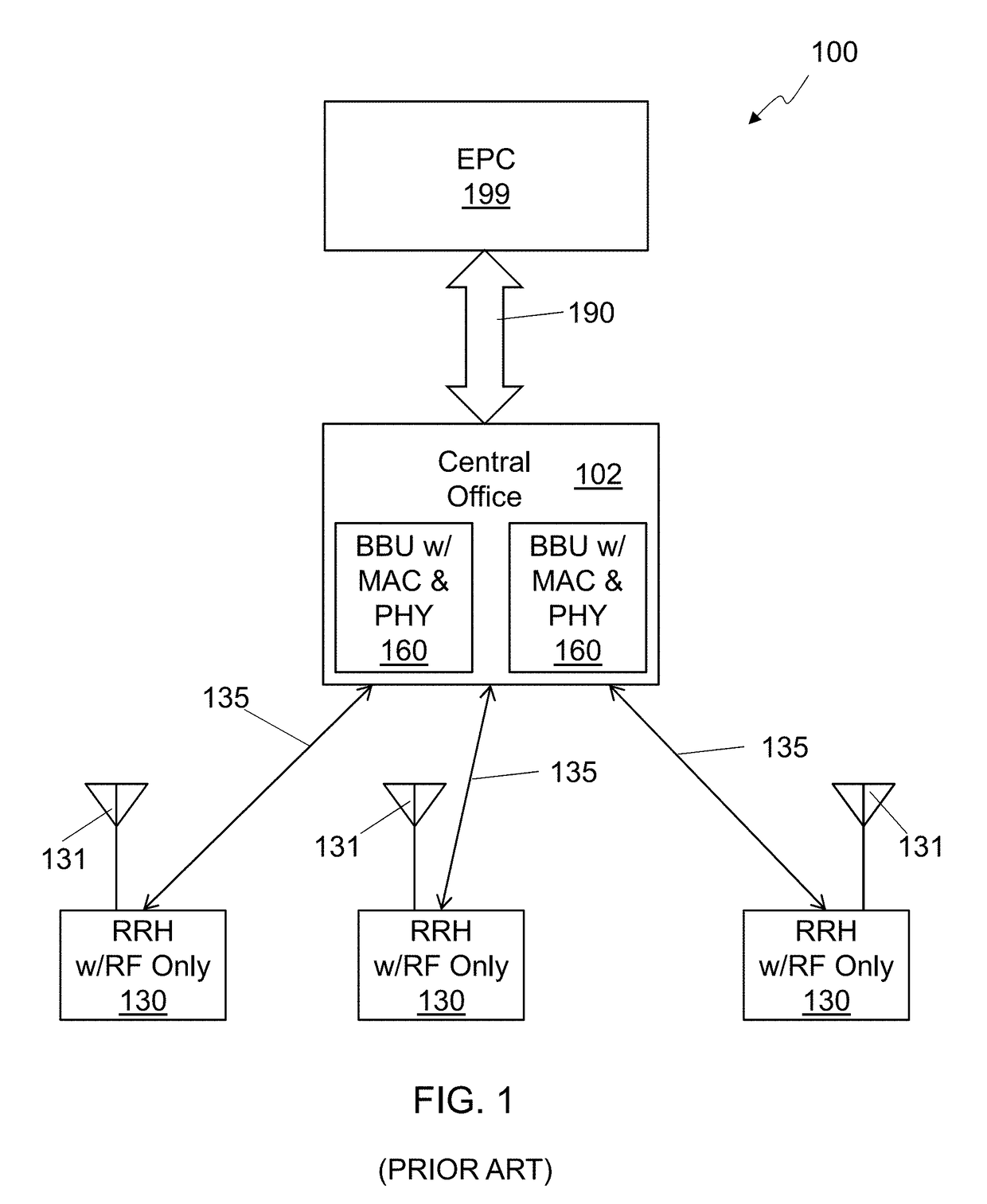
One key issue with a distributed RAN 100 architecture is latency.
If the overall latency for performing a specific function does not satisfy specific constraints imposed by the standard for the function, the system may fail, and communication between an eNB and a UE cannot be sustained.
Thus, latency constraints need to be satisfied in all operating conditions.
This requires hard, real-time, constraints on the processing of specific latency-constrained functions, or functions that have an impact on the overall system timeline.

Method used


Image

  • Remote Radio Unit with Adaptive Fronthaul Link for a Distributed Radio Access Network
  • Remote Radio Unit with Adaptive Fronthaul Link for a Distributed Radio Access Network
  • Remote Radio Unit with Adaptive Fronthaul Link for a Distributed Radio Access Network

Examples


first embodiment

[0337]In a first embodiment, a GPS signal is used by the RRU for synchronization. This may be accomplished by providing the RRU with a GPS receiver, from which GPS-grade atomic-clock level accuracy can be extracted.

second embodiment

[0338]FIG. 24 is a diagram showing carrier synchronization based on a downlink signal 2415, which is a RAN system 2400. In the second implementation, a downlink (DL) signal 2415 transmitted by at least one nearby eNB 2410 is used for synchronization. The signal 2415 may be at least one of a primary synchronization sequence (PSS), secondary synchronization sequence (SSS), physical broadcast channel (PBCH), cell-specific reference signal (CRS), or a combination thereof. The at least one signal may be received by the RRU 2430 via a dedicated RF receiver chain 2432, or by periodically retuning the existing receiver chain to the frequency used for transmission by the at least one nearby eNB 2410. In the latter case, the RRU 2430 may not be able to receive regular uplink signals while the receiver chain is used to receive the signal for the sake of synchronization. Uplink configuration and scheduling may be tuned so as to minimize the performance degradation stemming from skipping recepti...

third embodiment

[0339]FIG. 25 is a diagram showing carrier synchronization based on an uplink signal 2515, which is a RAN system 2500. An uplink signal 2515 transmitted by at least one nearby UE 2570 is used for synchronization. The nearby UE 2570 may be a dedicated beacon unit. The beacon unit 2570 may be located in an area with good GPS reception and with good propagation conditions from / to multiple RRUs 2530. The beacon unit 2570 may have a GPS-synchronized UE circuitry 2572 and baseband UE processing, possibly simplified (that is, lacking some features to reduce costs). The beacon unit 2570 may periodically attempt random access on the uplink frequency used by nearby RRUs 2530 for UL reception. Periodic random access attempts may sequentially target a different RRU 2530, that is, the UE embedded in the beacon unit 2570 may sequentially camp on each detectable RRU 2530 and perform at least one random access for each RRU 2530 after camping. The plurality of detected RRUs 2530 may be explored in a...


PUM


Abstract

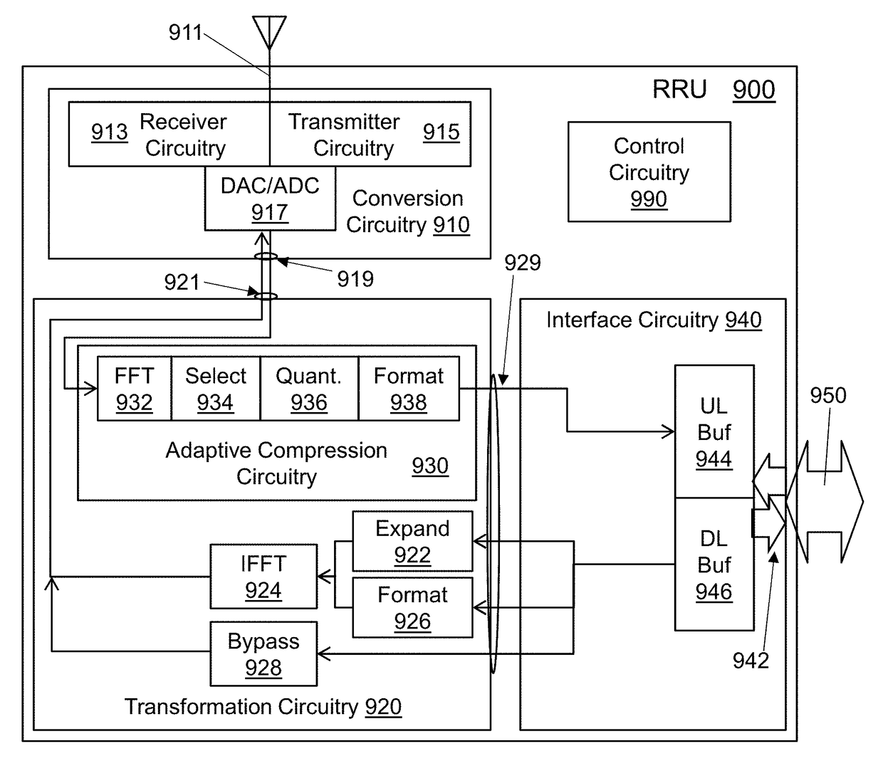
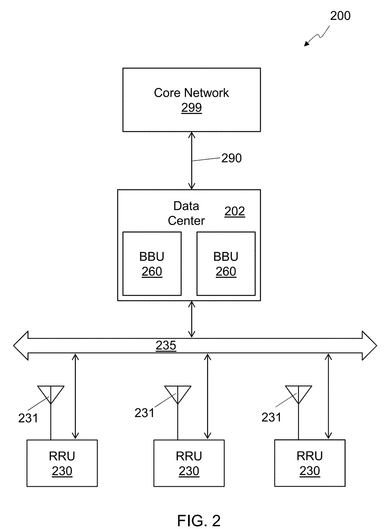
A distributed radio frequency communication system facilitates communication between a wireless terminal and a core network. The system includes a remote radio unit (RRU) coupled to at least one antenna to communicate with the wireless terminal. The RRU includes electronic circuitry to perform at least a first portion of a first-level protocol of a radio access network (RAN) for communicating between the wireless terminal and the core network. The system also includes a baseband unit (BBU) coupled to the core network, and configured to perform at least a second-level protocol of the RAN. A fronthaul link is coupled to the BBU and the RRU. The fronthaul link utilizes an adaptive fronthaul protocol for communication between the BBU and the RRU. The adaptive fronthaul protocol has provisions for adapting to conditions of the fronthaul link and radio network by changing the way data is communicated over the fronthaul link.

Description

CROSS-REFERENCE TO RELATED APPLICATIONS[0001]The present application is a continuation of U.S. patent application Ser. No. 15 / 549,381 entitled Baseband Unit with Adaptive Fronthaul link for a Distributed Radio Access Network which is a national stage application of International Patent Application PCT / US2016 / 022114, entitled DISTRIBUTED RADIO ACCESS NETWORK WITH ADAPTIVE FRONTHAUL and filed on Mar. 11, 2016, which claims priority to U.S. Provisional Patent Application No. 62 / 131,337, entitled Methods for Radio-as-a-Service, filed on Mar. 11, 2015. The entire contents of all three aforementioned applications are hereby incorporated by reference for any and all purposes.BACKGROUNDTechnical Field[0002]The present subject matter relates to wireless communication. More specifically, the present subject matter relates to a radio access network (RAN) using an adaptive fronthaul protocol.Background Art[0003]A Radio Access Network (RAN) provides access to a core network for a wireless termin...

Claims


Application Information

Patent Timeline
IPC IPC(8): H04L27/00H04B1/16H04W72/04H04L1/18H04B1/62H04L5/00H04L69/40
CPCH04L27/0002H04L1/1893H04B1/1661H04W72/0413H04B1/62H04L5/003H04L2027/003H04L25/02H04L69/04H04W88/085H04L27/2634H03M7/3059H04L69/321H04L69/40H04L9/40H04L65/40H04L69/32H04W72/21H04L27/26H04L1/0006H04L12/4604
Inventor FERTONANI, DARIOBARBIERI, ALAN
Owner COMMSCOPE TECH LLC
Learn More