Belt buckle and belt

a belt body and belt technology, applied in the field of belt buckles and belts, can solve the problems of increasing fairly expensive belt body production, etc., and achieve the effects of reducing the cost of belt body production, reducing the production cost of belts, and improving flexibility and strength

Active Publication Date: 2018-01-04
POLYMER GEAR
View PDF0 Cites 3 Cited by
  • Summary
  • Abstract
  • Description
  • Claims
  • Application Information

AI Technical Summary

Benefits of technology

[0021]According to the present invention, it is possible to produce the belt body of the belt by use of a molding process which includes supplying melted synthetic resin into a mold and continuously drawing the core out of the mold, and thereby a production process of the belt body becomes simpler than that of a conventional belt body, and thereby the cost of production of t...

Problems solved by technology

However, production of this belt body is fairly costly, so...

Method used


Image

  • Belt buckle and belt
  • Belt buckle and belt
  • Belt buckle and belt

Examples


Embodiment Construction

[0036]A preferred embodiment of the present invention will be described below with reference to accompanying drawings.

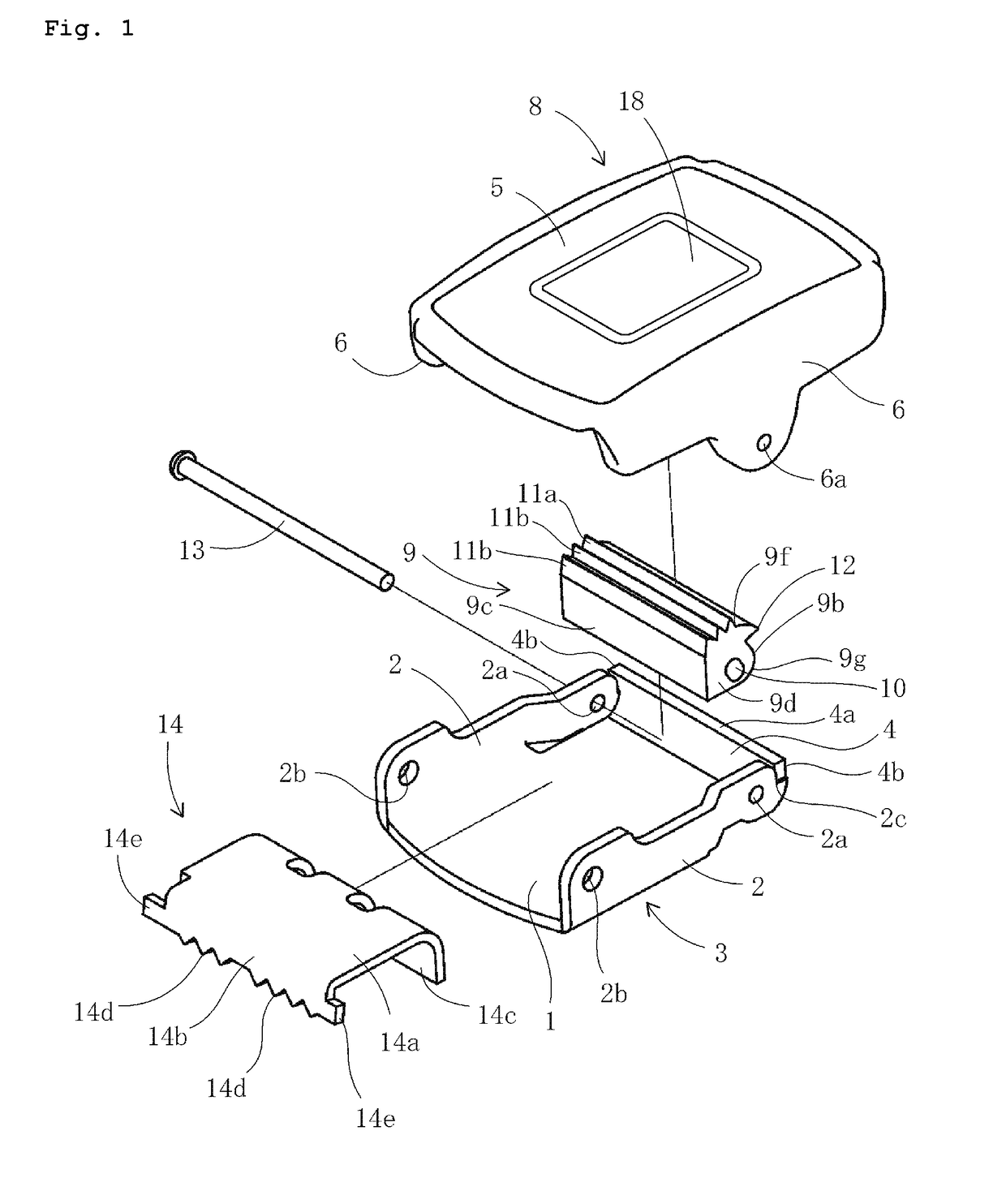
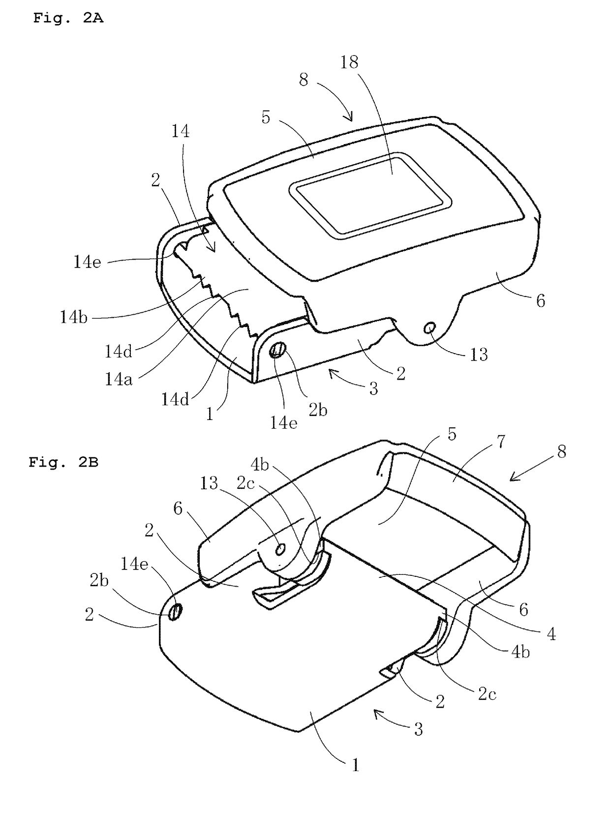
[0037]FIG. 1 is an exploded perspective view of a belt buckle according to an embodiment of the present invention. FIG. 2A is a perspective view of the belt buckle of FIG. 1 as seen obliquely from above, and FIG. 2B is a perspective view of the belt buckle of FIG. 1 as seen obliquely from below.

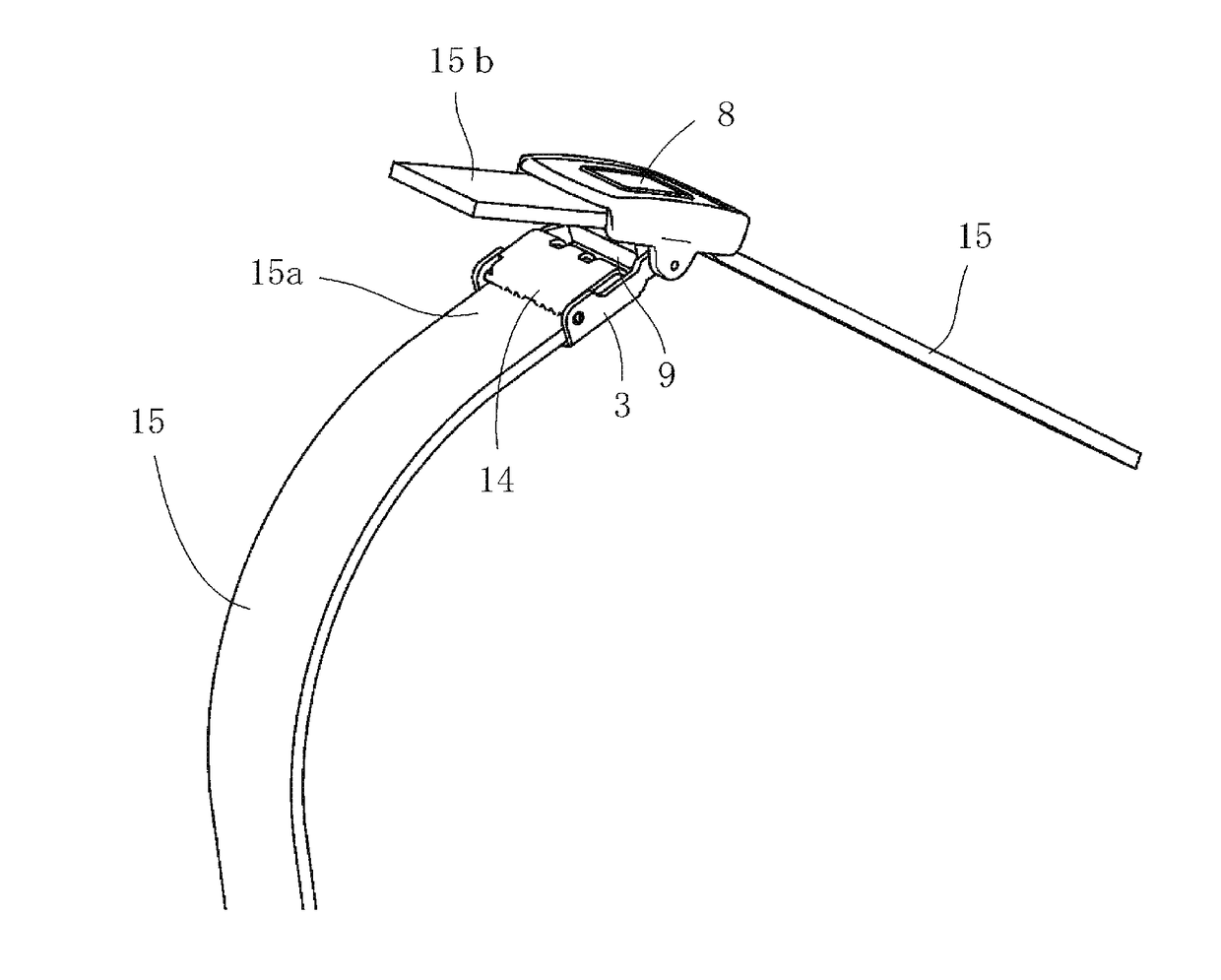
[0038]FIG. 3A is a side view of the belt buckle of FIG. 1, in which a cover member of the belt buckle is arranged at a closed position, and FIG. 3B is a side view of the belt buckle of FIG. 1, in which the cover member of the belt buckle is arranged at an opened position. FIG. 4A is a perspective view of a belt provided with the belt buckle shown in FIG. 1, and FIG. 4B is an enlarged sectional side view of the belt buckle of the belt of FIG. 4A.

[0039]Referring to FIGS. 1 through 4, a belt buckle of the present invention comprises a base member 3 formed by a first bottom wall 1...


PUM


Abstract

Base and cover members 3, 8 are pivotally connected by a pin 13. The cover member can be rotated between an opened position and a closed position. A stopper member 9 with first and second claws is mounted on the pin to rotate around the pin. The cover member has an engagement wall 7. An end 15b of a belt 15 is inserted through the cover member, the cover member is rotated from the opened position to the closed position, and the belt is pulled in a direction of drawing the belt out of the belt buckle, and thereby, the belt is locked between the second claws and a bottom wall 5 of the cover member. At the same time, the rotational moment rotating the cover member toward the closed position is generated by the engagement wall of the cover member being pressed by the belt.

Description

FIELD OF THE INVENTION[0001]The present invention relates to a belt buckle and a belt provided with the belt buckle.BACKGROUND OF THE INVENTION[0002]JP 2013-138796 A discloses a belt buckle having base and cover members which overlap and are pivotally connected to each other by a pin in such a way that the cover member is rotatable around the pin between an opened position and a closed position. The base member has a belt holding mechanism cooperating with the second bottom wall of the cover member in the closed position of the cover member.[0003]The belt holding mechanism comprises a restraint wall connecting to one end of the first bottom wall of the base member, and a stopper member mounted on the pin so as to rotate around the pin and extended between a pair of first side walls of the base member. The stopper member has a bottom surface, a pair of side surfaces, a pair of end surfaces, an upper surface, and a through hole extending through the end surfaces in a longitudinal dire...

Claims


Application Information

Patent Timeline
IPC IPC(8): A44B11/12A41F9/00
CPCA41F9/002A44B11/12
Inventor FUKUI, HIROAKIFUKUI, HIROTAKAHASE, NAOYUKI
Owner POLYMER GEAR
Why Eureka
Try Eureka