Multi-port ball valve with induced flow in ball-body cavity

a multi-port, ball valve technology, applied in multiple-way valves, plug valves, engine components, etc., can solve the problems of unsatisfactory steam addition, steam supply can have problems of its own, and steam may not always be available in the quantity and pressure needed, so as to prevent fluid stagnation

Active Publication Date: 2018-01-04
VELAN INC
View PDF4 Cites 8 Cited by
  • Summary
  • Abstract
  • Description
  • Claims
  • Application Information

AI Technical Summary

Benefits of technology

[0023]In this embodiment, a rapid exchange of fluid in the cavities of the body and around the metal bellows-type seat seals prevents stagnation of the fluid.
[0024]A first method provides holes in the top of the ball, leaving a gap between the bottom of the ball and the body, and making a tapered body bore reduction to create a Venturi suction effect at the annular space between the ball and the body close to the ball and body inlets. Using this method, a part of the stream will be deflected up to flow through holes in the top of the ball and into the ball / body cavity, flow downwards around the ball in the cavity, and flow out of that cavity at the bottom of the ball. The switch valve body inlet may include a tapered body bore towards the ball inlet. In this method, the flow through the ball / body cavity would be in the reverse direction to the main stream that flows through the ball bore to achieve a body cavity flush.

Problems solved by technology

Unfortunately, process-wise, it is undesirable to add the required amount of steam because it has an unwanted cooling effect, and it must later be disposed of as foul water.
The steam supply can have problems of its own.
The steam may not always be available in the quantity and pressure needed due to unanticipated large demand elsewhere, supply system equipment failure, operator errors, or other problems.

Method used


Image

  • Multi-port ball valve with induced flow in ball-body cavity
  • Multi-port ball valve with induced flow in ball-body cavity
  • Multi-port ball valve with induced flow in ball-body cavity

Examples


Embodiment Construction

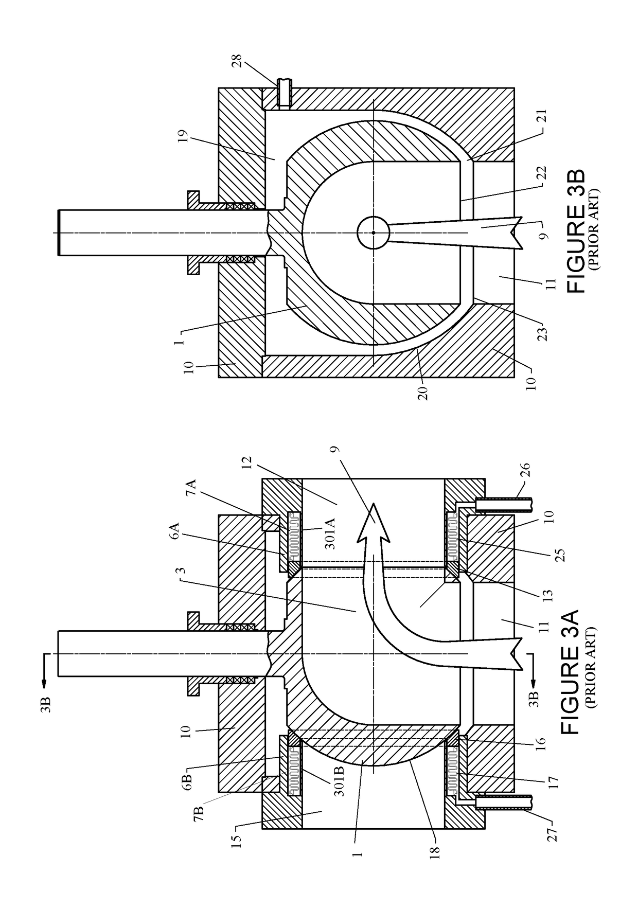
[0036]FIGS. 1A, 1B, 2, 3A and 3B illustrate a typical type of switch valve that is improved upon by the example embodiments described herein.

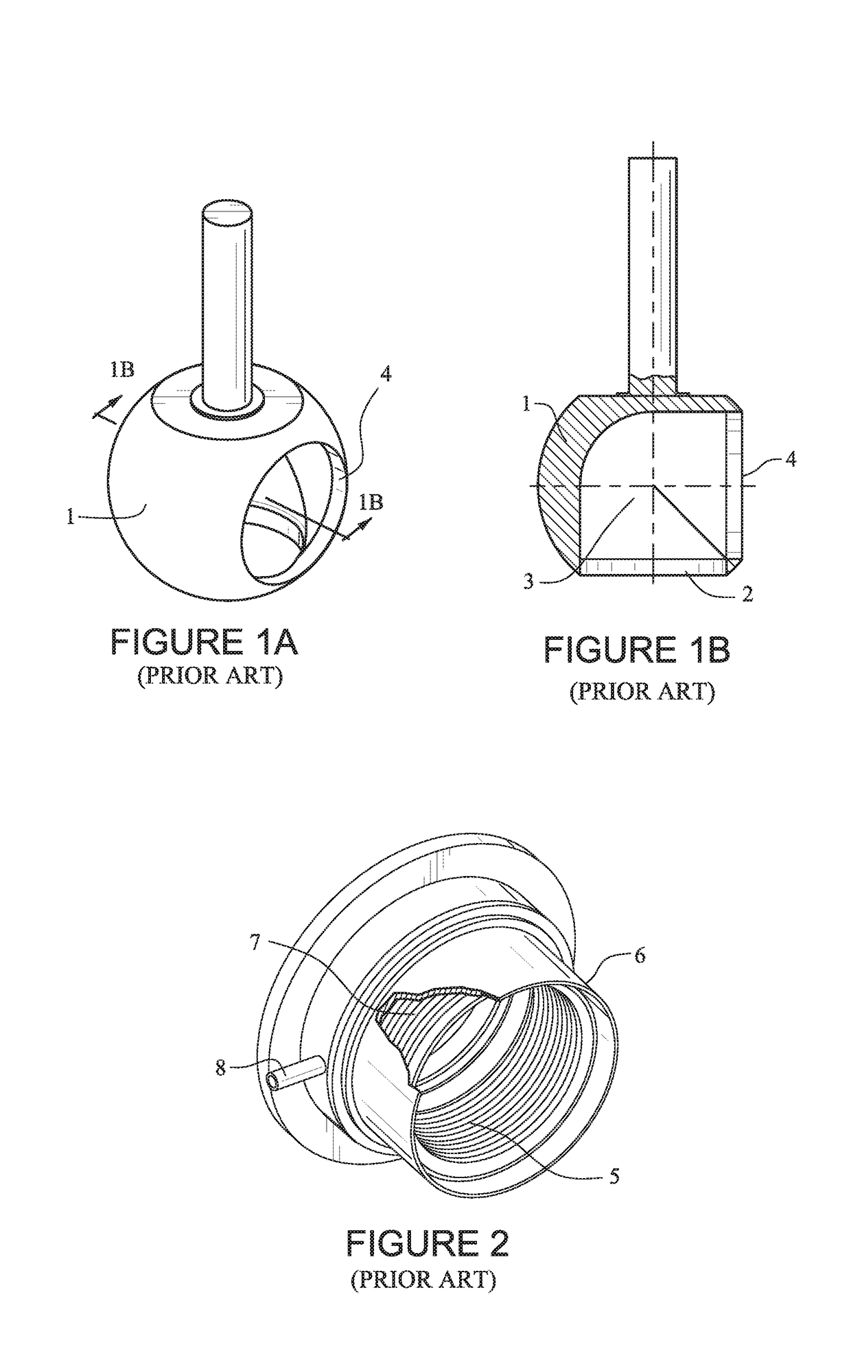
[0037]FIGS. 1A and 1B depict an unimproved ball that has been, and remains, in constant use in switch valves of oil refineries around the world, dating from the 1970's. FIG. 1A is a perspective view and the sectional view in FIG. 1B along cross-sectional line 1B-1B shows that the ball (1) has an inlet port (2), a 90-degree turn flow passage (3) through it, and an exit port (4). Heavy oil enters the ball (1) at the inlet port (2), and the oil is diverted 90 degrees by the turn in the flow passage (3) in the ball (1), then exits through the exit port (4).

[0038]FIG. 2 depicts a metal bellows (5) that serves as a back-of-seat seal, also known as a bellows-type seat seal, residing in a flanged tubular member (6) that supports the metal bellows (5) and the seat (not shown in this figure). The unimproved flanged tubular support (6) has been cut away t...


PUM


Abstract

A multiport ball valve body has one entry port and at least two exit ports disposed transversely to the ball valve body entry port. A ball disposed in the body has one entry port and one exit port that is disposed transversely to the ball entry port. The ball can be rotated to selectively align the ball exit port with one of the at least two body exit ports. Holes through the ball admit part of the fluid flow into the cavity between the ball and the body, and internal parts are exposed, such that the cavity and the internal parts are kept flushed.

Description

CROSS-REFERENCE TO RELATED APPLICATION[0001]This application claims priority benefit of U.S. provisional application 62 / 117,508 filed in the U.S. Patent and Trademark Office on Feb. 18, 2015. The entire contents of this U.S. provisional application 62 / 117,508 is hereby incorporated herein by reference.BACKGROUND[0002]In the field of refining petroleum crude oil, a process unit called the Delayed Coker increases the yield of gasoline and other high grade products by reprocessing heavy bottom oil from one of the other process units called the Fractionator, adding value of tens of thousands of dollars per day. In the Delayed Coker process unit, the heavy oil is first passed through heaters, then passed through a special multi-port metal-seated ball-type diverter valve, called the “switch valve”, which is one application for this invention.[0003]The switch valve diverts the flow of heated heavy oil into two large drums, or into a third drum bypass connection. The heated oil remains as l...

Claims


Application Information

Patent Timeline
Patent Type & Authority Applications(United States)
IPC IPC(8): F16K5/06F16K11/087
CPCF16K5/0605F16K11/0876F16K5/0689F16K5/207
Inventor KINDERSLEY, PETER GEOFFREYZEDICK, KYLE PHILLIP
Owner VELAN INC
Why Eureka
Try Eureka