Plate heat exchanger

A technology of plate heat exchangers and heat exchange elements, which is applied in the direction of heat exchange equipment, heat exchanger types, heat exchanger shells, etc., and can solve the problems of reducing fluid fluidity and heat exchange efficiency

Active Publication Date: 2012-03-28
ERAE AUTOMOTIVE SYST
View PDF7 Cites 19 Cited by
  • Summary
  • Abstract
  • Description
  • Claims
  • Application Information

AI Technical Summary

Problems solved by technology

[0005] Therefore, the fluid in the flow channel flows along the grooves 1a, 2a of the plates 1, 2 so that the flow direction of the fluid is limited to the oblique direction on one side, and the fluid can easily pass through the recesses 1c, 2c around the through holes 1b, 2b. stagnation, greatly reducing the fluidity of the fluid, and the reduction in fluidity leads to a decrease in heat exchange efficiency

Method used


Image

  • Plate heat exchanger
  • Plate heat exchanger
  • Plate heat exchanger

Examples


Embodiment Construction

[0024] Preferred embodiments of the present invention will be described in detail below in conjunction with the accompanying drawings.

[0025] Figure 1 to Figure 7 A plate heat exchanger according to one embodiment of the present invention is shown.

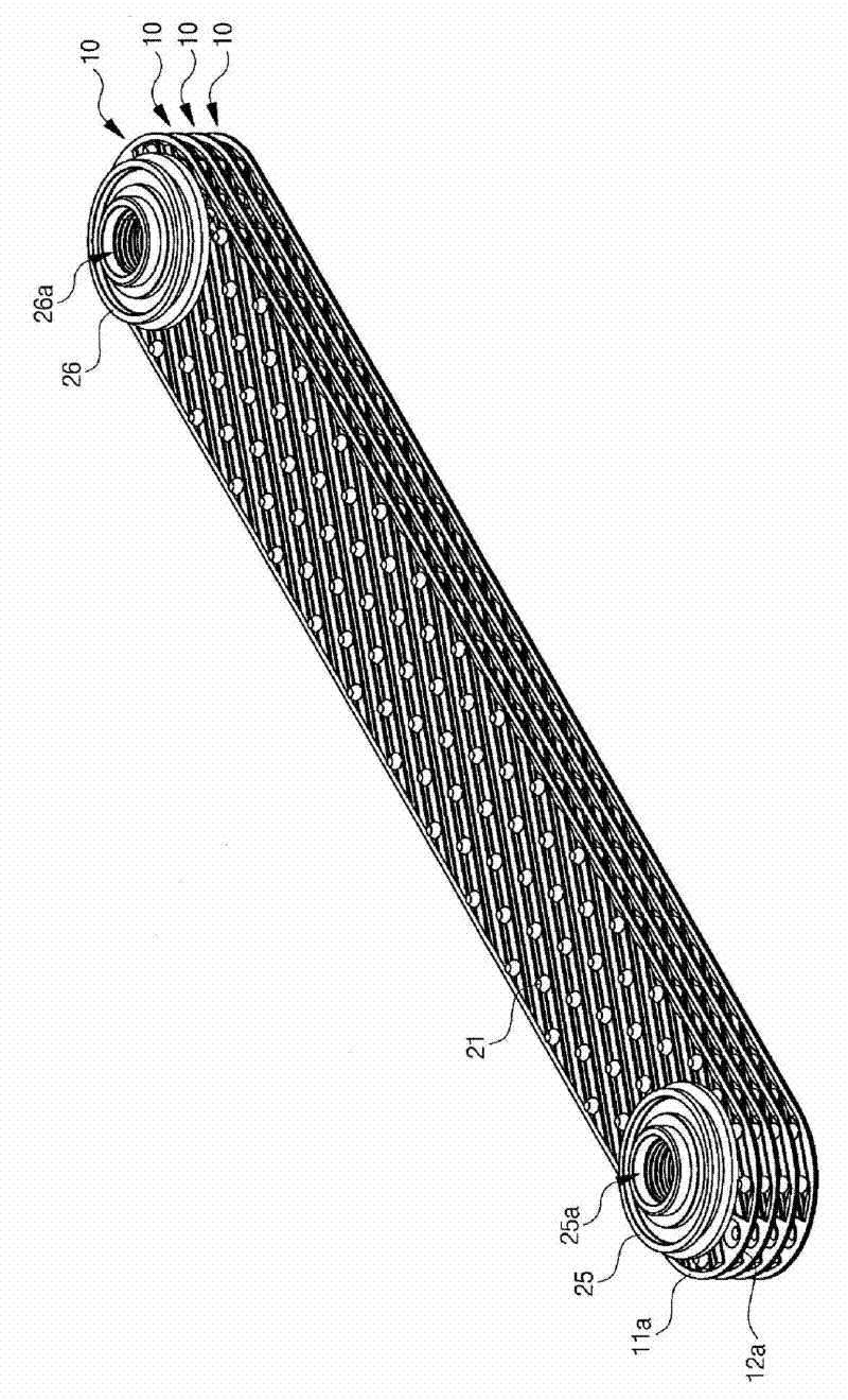
[0026] Such as figure 1 As shown, the plate heat exchanger of the present invention includes a plurality of heat exchange elements 10 (heat exchange elements), and the plurality of heat exchange elements 10 are stacked up and down.

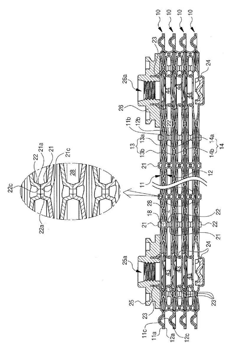
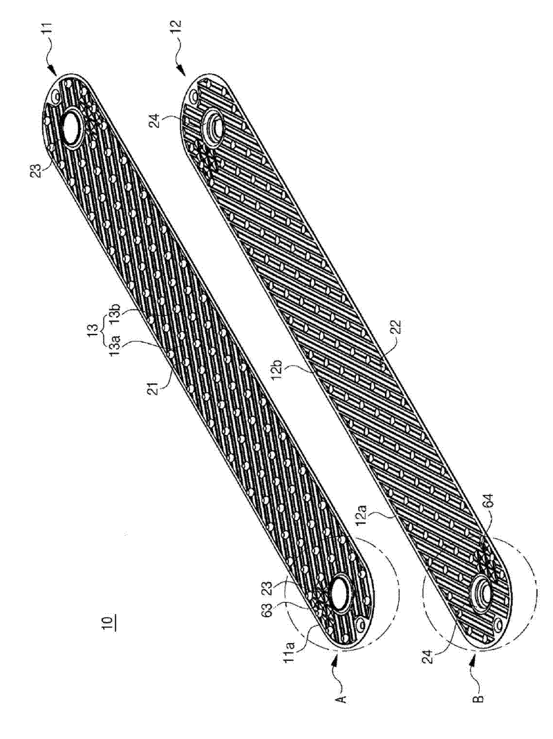
[0027] Such as figure 2 As shown, each heat exchange element 10 is equipped with a first flow channel 18 through which a first fluid such as oil or refrigerant passes. Each heat exchange element 10 is formed by combining an upper plate 11 and a lower plate 12 . The upper plate 11 and the lower plate 12 are made of a metal material with excellent thermal conductivity such as aluminum, and the edges 11a, 12a of the upper plate and the lower plate 11, 12 can be bonded to each other by brazing or ...


PUM


Abstract

The present invention relates to a plate heat exchanger for largely improving heat exchange efficiency by improving the flow of fluids. The plate heat exchanger of the present invention comprises a plurality of heat exchange tubes stacked in the vertical direction, each formed by coupling upper and lower plates with each other, and each having a 1st flow channel in which a 1st fluid flows, and a 2nd flow channel formed between the heat exchange tubes for the flow of a 2nd fluid, wherein each of the heat exchange tubes has an inlet path and an outlet path separated from each other on both ends, the upper plate has an upper flange protruded from the upper parts of the inlet path and the outlet path, the lower plate has a lower flange protruded from the lower parts of the inlet path and the outlet path,; a plurality of upper flow grooves are extended in an oblique direction on the bottom surface of the upper plate, a plurality of lower flow grooves are extended in an oblique direction on the top surface of the lower plate, the upper plate and the lower plate form the first flow channel by being coupled with each other in such a manner that the upper flow grooves and the lower flow grooves intersect each other, and in the periphery of the inlet path and the outlet path of the upper plate and in the periphery of the inlet path and the outlet path of the lower plate are provided structures for guiding the flow of the fluids in two or more directions.

Description

technical field [0001] The invention relates to a plate heat exchanger, in particular to a plate heat exchanger which improves the flowability of fluid and greatly improves the heat exchange efficiency. Background technique [0002] A heat exchanger is a device that transfers heat from a higher temperature fluid to a lower temperature fluid through a heat transfer wall. The heat exchanger is mainly used in vehicle interior air conditioning systems, transmission oil coolers, etc. The heat exchanger needs to be compact in size in order to cope with the narrowing of the installation space, so that the plate heat exchanger has been widely used. [0003] The plate heat exchanger includes a plurality of heat exchange elements stacked facing each other in such a manner that flow passages are formed between adjacent plates. The flow channel is divided into two or more flow channels through which different media pass. Thus, the dissimilar heat exchange media exchange heat through e...

Claims


Application Information

Patent Timeline
Patent Type & Authority Applications(China)
IPC IPC(8): F28D9/00F28F3/02
CPCF28F9/026F28D1/0333F28F3/044F28D9/0043F28F3/042F28F3/046F28D9/00F28F3/02
Inventor 韩相哲崔信一金洛均
Owner ERAE AUTOMOTIVE SYST
Why Eureka
Try Eureka