Slotted impingement plates for heat exchangers

Inactive Publication Date: 2011-09-22
SAUDI ARABIAN OIL CO
View PDF23 Cites 8 Cited by
  • Summary
  • Abstract
  • Description
  • Claims
  • Application Information

AI Technical Summary

Benefits of technology

[0009]The improved impingement plate of the present invention for use in a shell and tube heat exchanger are positioned between the inlet openings and the tubes, the surfaces of the plates being normal to the flow path of the liquid entering the shell from the inlet openings and are provided with a plurality of openings through which a portion of the liquid passes before contacting the tubes. In one aspect of the invention, the openings are formed as elongated parallel slots and the

Problems solved by technology

In many conventional shell and tube type heat exchangers the impingement plate adjacent the inlet nozzle protects the tubes from direct impact of the high velocity inlet fluid, but often creates operational problems when fluid flowing downstream of the impingement plate has reduced velocity due to the vortex effect of fluid motion at the sides of the impingement plate.
This results in fouling accumulation on surfaces of the tubes, particularly in the region designated herein as “fouling area” immediately downstream from the conventional impingement pla

Method used


Image

  • Slotted impingement plates for heat exchangers
  • Slotted impingement plates for heat exchangers
  • Slotted impingement plates for heat exchangers

Examples


Example

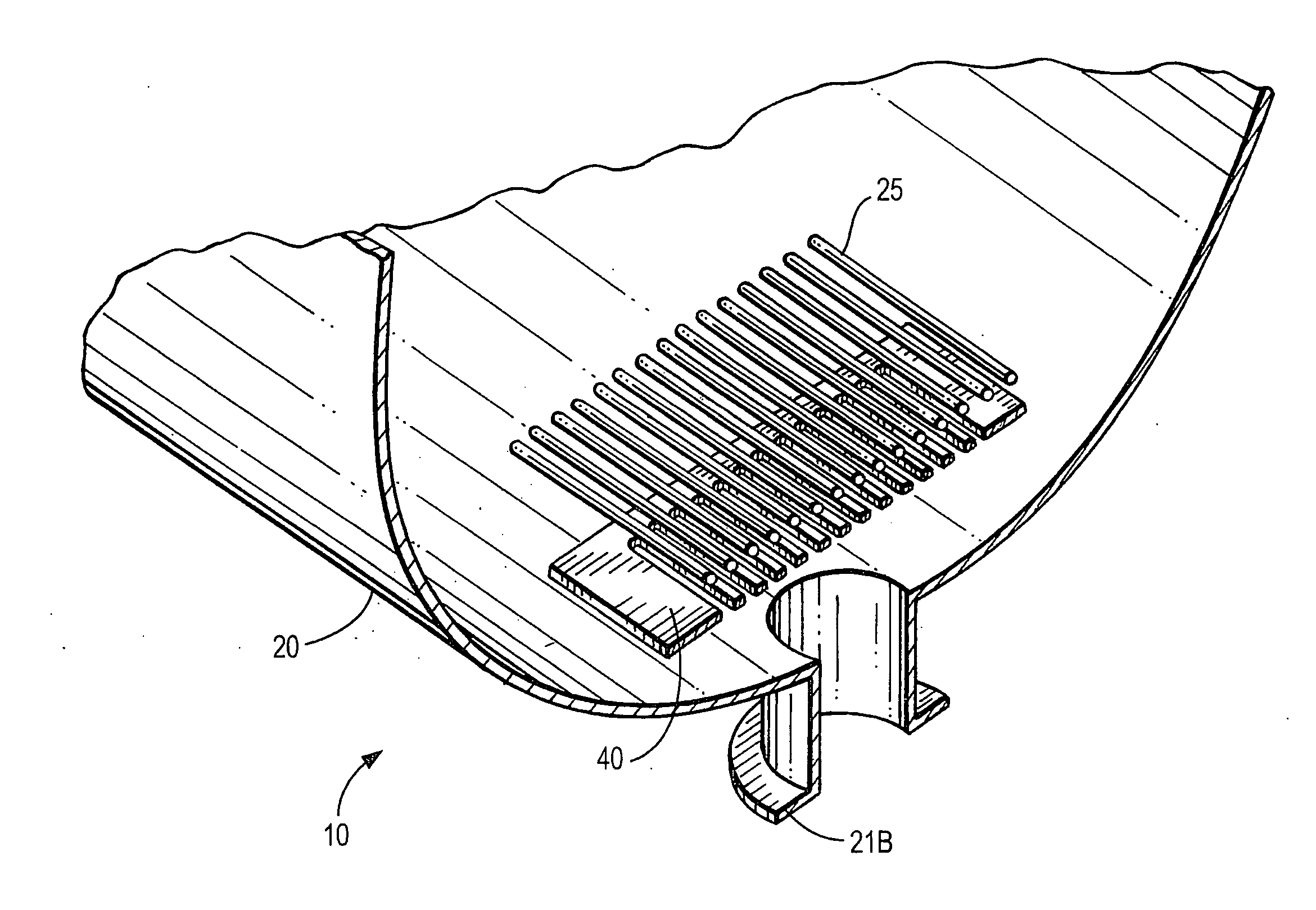
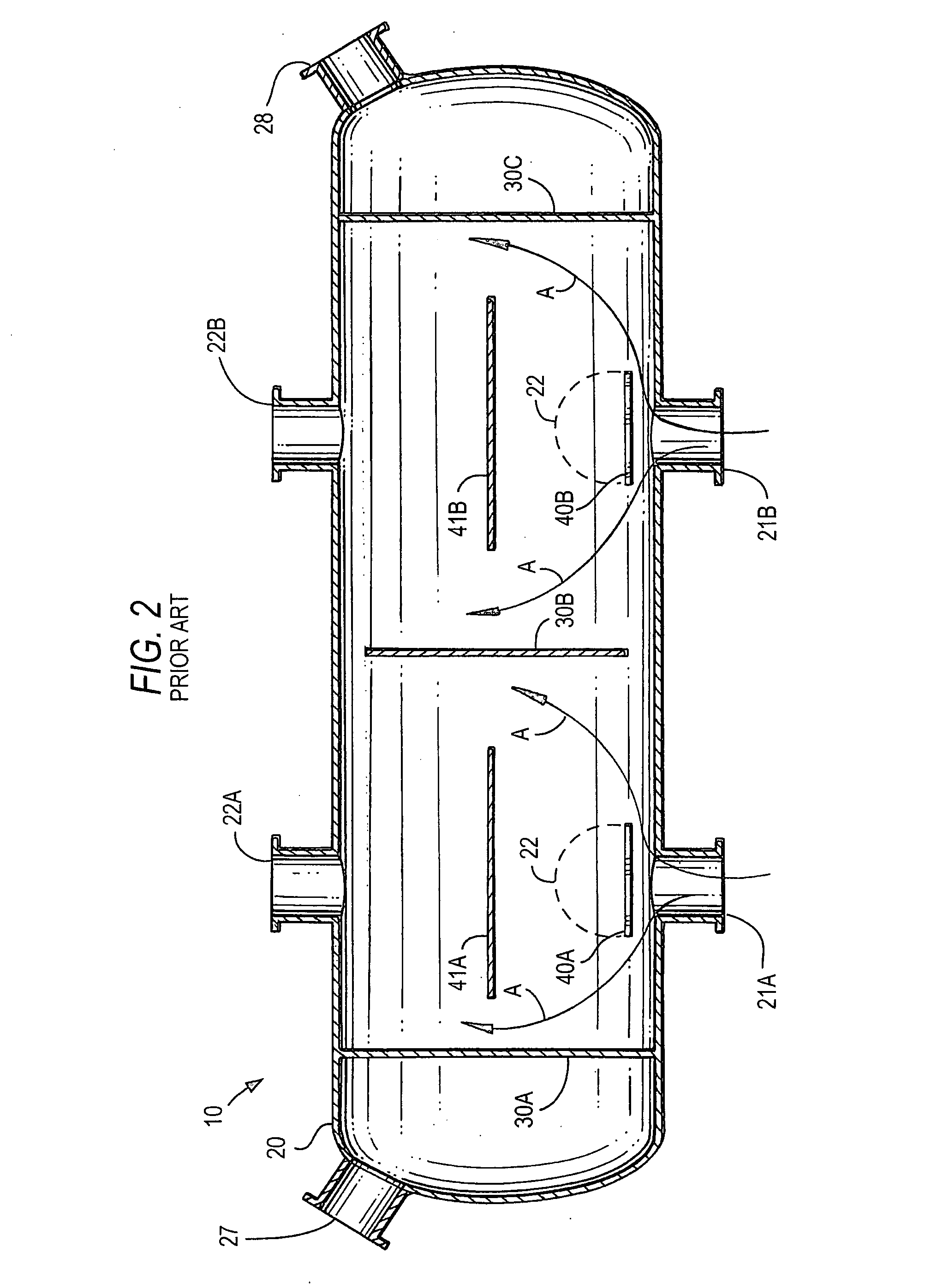
[0015]A preferred embodiment of the impingement plate of the invention is illustrated in FIGS. 3-4. For simplicity and clarity, the heat exchanger 10 in FIG. 4 will be shown as having the same housing or shell 20 as in FIGS. 1-2 and also having the same inlets 21A, 21B, outlets 22A, 22B and bundle of tubes 25. As mentioned above, in the present embodiments it is understood that flowing in these tubes 25 is a relatively hot fluid, with heat transfer from the outer surfaces of these tubes 25 to the relatively cooler second fluid flowing from inlets 21A, 21B through the shell housing to outlets 22A, 22B.

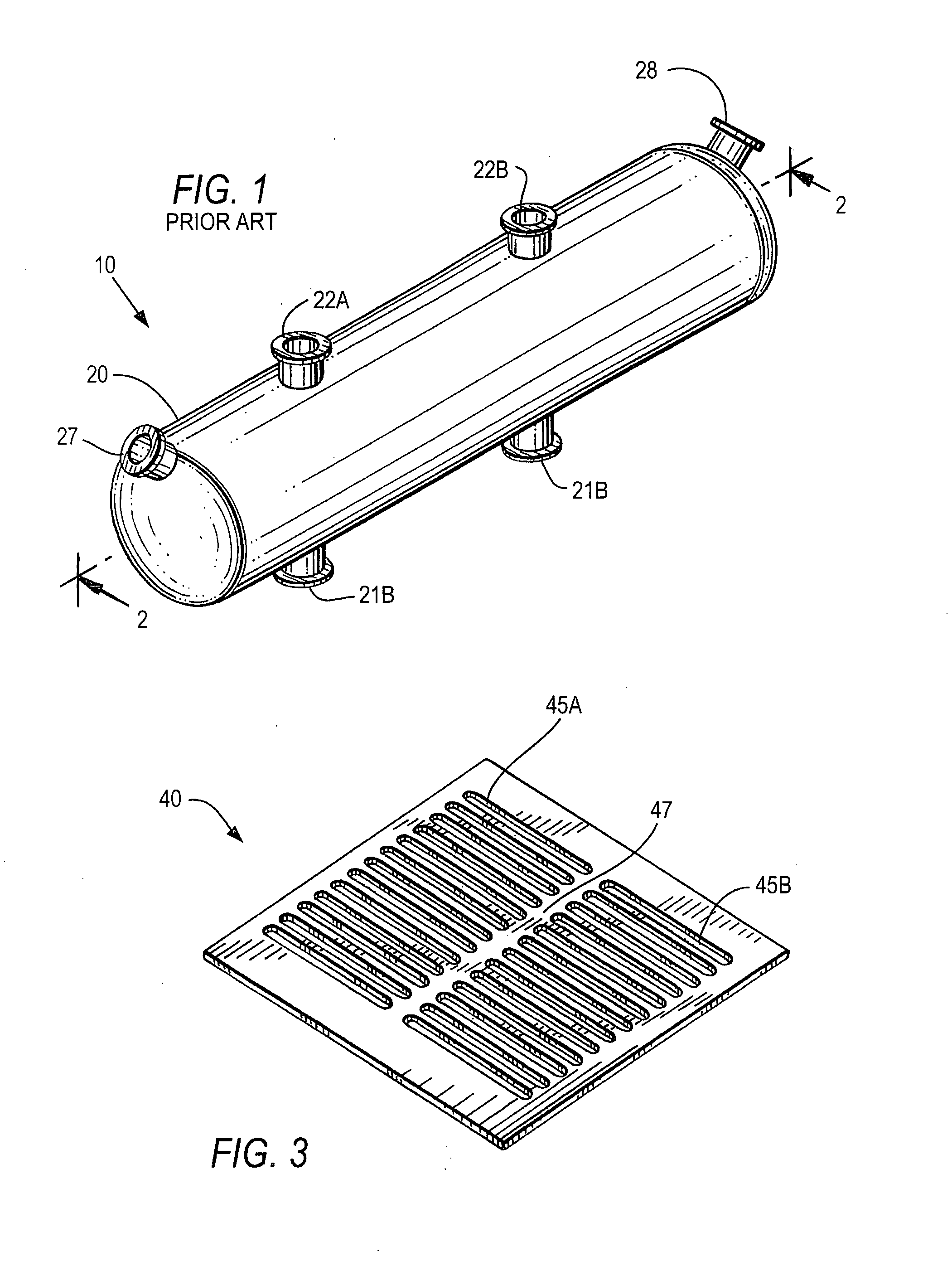
[0016]FIGS. 3-4 illustrate in the heat exchanger housing 20, the impingement plate 40 which is generally planar. Although the impingement plate 40 is shown as being rectilinear, other shapes can be used. The impingement plate 40 includes a plurality of openings 45A, 45B through which a portion of the shell-side fluid passes before contacting the tubes. The openings are preferably in the...


PUM


Abstract

Impingement plates for shell and tube heat exchangers are positioned between the inlet openings and the tubes with the surfaces of the impingement plates being normal to the flow path of the liquid entering the shell from the inlet openings and having a plurality of openings through which a portion of the liquid passes before contacting the tubes. The openings can be formed as elongated parallel slots that are positioned parallel to the tubes and function to enhance the fluid flow, especially in the area that is immediately downstream from the impingement plates, thereby reducing fluid stagnation, fouling and tube erosion and prolonging the useful life and time in service between maintenance shut downs.

Description

FIELD OF THE INVENTION[0001]The invention relates to impingement plates for shell and tube heat exchangers.BACKGROUND OF THE INVENTION[0002]Fluid heat exchangers are widely used in the industry. One common heat exchanger is known as a shell and tube heat exchanger and includes a cylindrical housing or shell encompassing a bundle of tubes. In this type of heat exchanger, heat from a first fluid flowing through the tubes is transferred to a second fluid flowing through the housing, as a result of the second fluid flowing in contact with the outer surfaces of said tubes. The second fluid enters the shell through a nozzle and is directed initially to an impingement plate which deflects and redirects the second fluid to flow toward and about the outer surfaces of said tubes, as generally disclosed in U.S. Pat. No. 3,938,588.[0003]The inlet fluid initially has a high velocity and dynamic force when it impacts on the impingement plate. In many conventional shell and tube type heat exchange...

Claims


Application Information

Patent Timeline
IPC IPC(8): F28F1/00
CPCF28D7/16F28F9/0278F28F9/0265
Inventor AL-ANIZI, SALAMAH S.AL-OTAIBI, DHAWI A.AL-QAHTANI, ABDULLAH M.AL-HADHRAMI, LUAI M.
Owner SAUDI ARABIAN OIL CO
Why Eureka
Try Eureka