Methods and system for enhancing flow of a fluid induced by a rod pumping unit

Active Publication Date: 2016-06-23
RAVDOS HLDG INC
View PDF6 Cites 3 Cited by
  • Summary
  • Abstract
  • Description
  • Claims
  • Application Information

AI Technical Summary

Benefits of technology

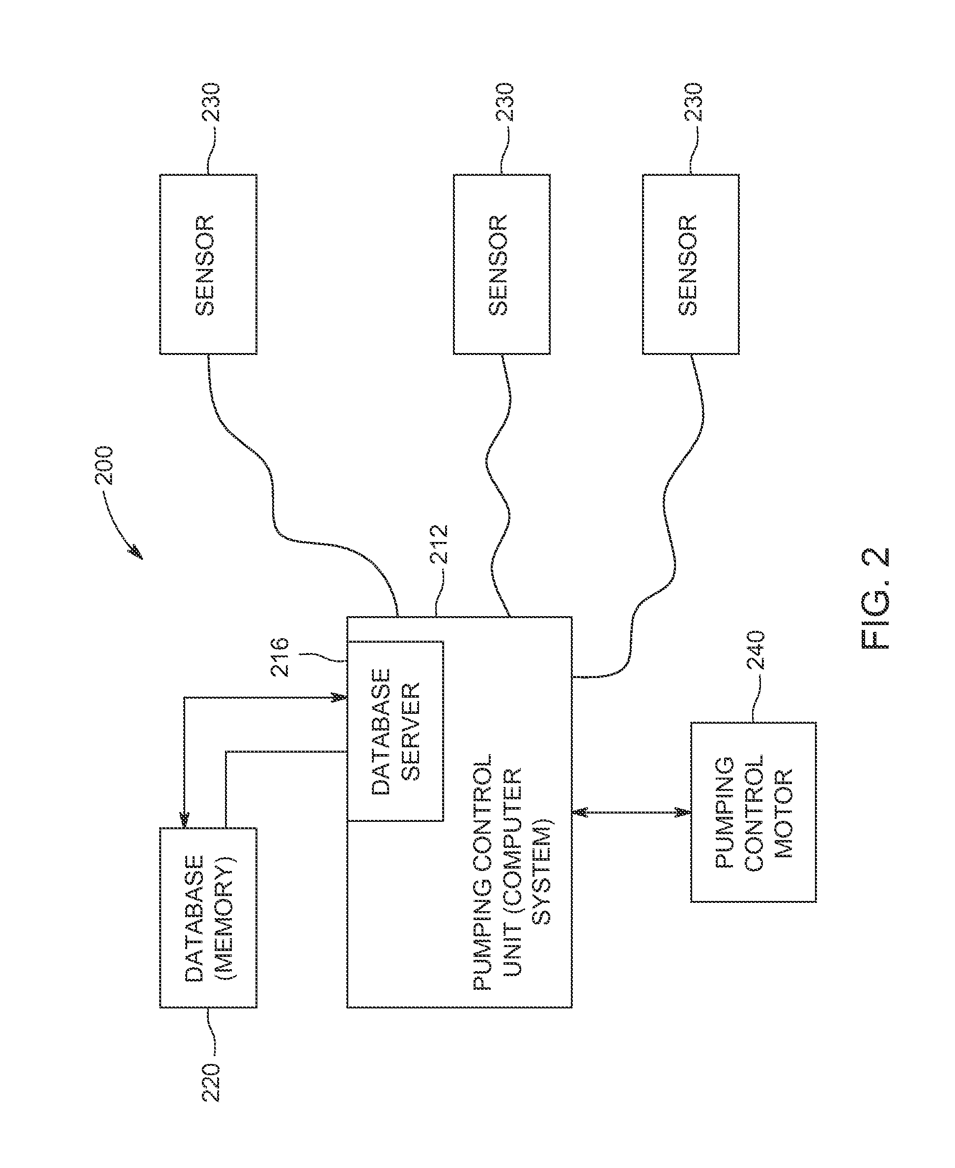
[0005]In one aspect, a system for enhancing a flow of a fluid induced by a rod pumping unit is provided. The system includes one or more sensors configured to monitor one or more conditions of the rod pumping unit and generate signals representing sensor data based on the one or more conditions and a pumping control unit comprising a processor and a memory. The pumping control unit is in communication with the one or more sensors and is configured to control stroke movement of the rod pumping unit, thereby controlling the flow of the fluid induced by the rod pumping unit. The pumping control unit is configured to (a) initiate at least one stroke of the rod pumping unit. The at least one stroke is based on current stroke timing data, and the current stroke timing data includes a value for strokes per minute (SPM). The pumping control unit is also configured to (b) receive signals representing sensor data from the one or more sensors, (c) upon a determination of, based on the sensor data, a violation of a first set of constraints, make a first adjustment to the current stroke timing, and return to step (a), (d) upon a determination of, based on the sensor data, a violation of a second set of constraints, make a second adjustment to the current stroke timing, and return to step (a), and (e) upon a determination of, based on the sensor data, no violation

Problems solved by technology

Furthermore, well conditions, such as downhole pressure, may change over time.
These conditions may cause variability in the flow of the fluid.
In addition, these conditions affect the sucker rod string.
Traveling stress waves from

Method used


Image

  • Methods and system for enhancing flow of a fluid induced by a rod pumping unit
  • Methods and system for enhancing flow of a fluid induced by a rod pumping unit
  • Methods and system for enhancing flow of a fluid induced by a rod pumping unit

Examples


Embodiment Construction

[0019]In the following specification and the claims, reference will be made to a number of terms, which shall be defined to have the following meanings.

[0020]The singular forms “a”, “an”, and “the” include plural references unless the context clearly dictates otherwise.

[0021]“Optional” or “optionally” means that the subsequently described event or circumstance may or may not occur, and that the description includes instances where the event occurs and instances where it does not.

[0022]Approximating language, as used herein throughout the specification and claims, may be applied to modify any quantitative representation that may permissibly vary without resulting in a change in the basic function to which it is related. Accordingly, a value modified by a term or terms, such as “about”, “approximately”, and “substantially”, are not to be limited to the precise value specified. In at least some instances, the approximating language may correspond to the precision of an instrument for m...


PUM


Abstract

A system for enhancing a flow of a fluid induced by a rod pumping unit is provided. The system includes one or more sensors and a pumping control unit configured to control stroke movement of the rod pumping unit. The pumping control unit is configured to: (a) initiate at least one stroke of the rod pumping unit; (b) receive sensor data from the one or more sensors; (c) upon determination of a violation of a first set of constraints, make a first adjustment to the current stroke timing, and return to step (a); (d) upon determination of a violation of a second set of constraints, make a second adjustment to the current stroke timing, and return to step (a); and (e) upon determination of no violation of at least one set of constraints make a third adjustment to the current stroke timing, and return to step (a).

Description

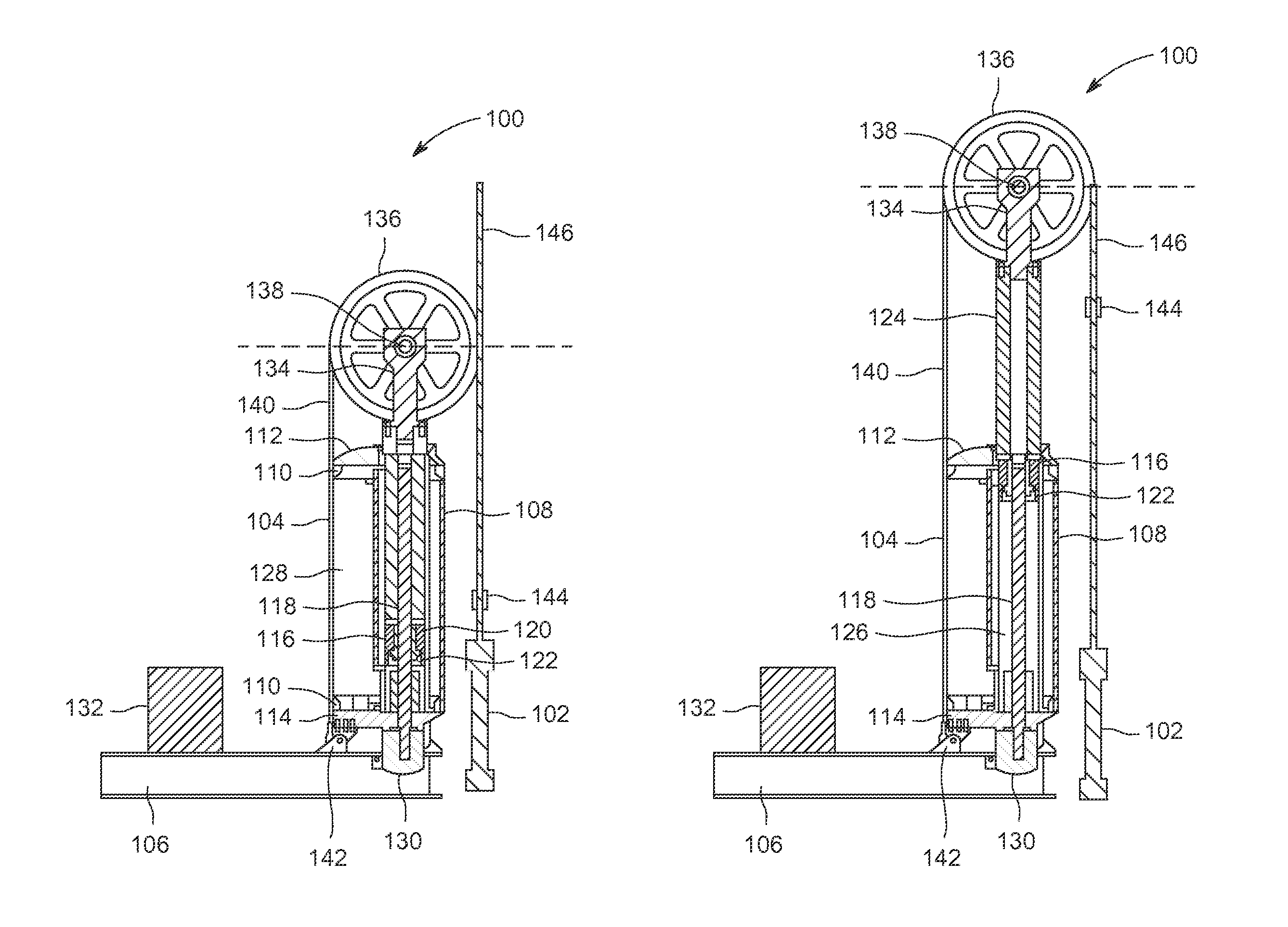
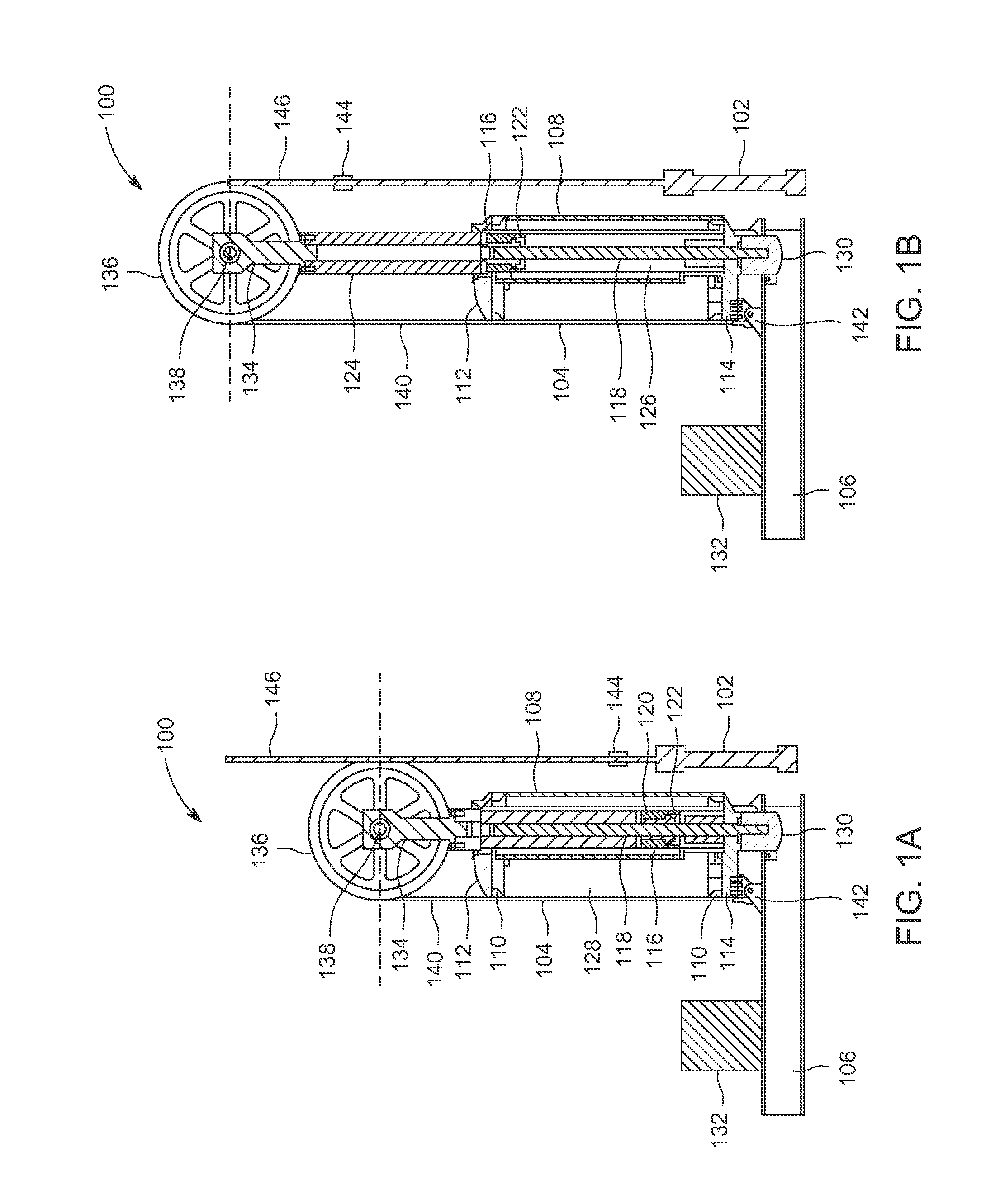
BACKGROUND[0001]The field of the invention relates generally to controlling rod pumping units, and more specifically, to methods and a system for controlling a rod pumping unit to enhance the flow of a fluid induced by the rod pumping unit.[0002]Most known rod pumping units (also known as surface pumping units) are used in wells to induce fluid flow, for example oil and water. The primary function of the linear pumping unit is to convert rotating motion from a prime mover (e.g., an engine or an electric motor) into reciprocating motion above the wellhead. This motion is in turn used to drive a reciprocating down-hole pump via connection through a sucker rod string. The sucker rod string, which can extend miles in length, transmits the reciprocating motion from the wellhead at the surface to subterranean valves in a fluid bearing zone of the well. The reciprocating motion of the valves induces the fluid to flow up the length of the sucker rod string to the wellhead.[0003]The rod pump...

Claims


Application Information

Patent Timeline
IPC IPC(8): F04B49/12F04B47/02F04B51/00
CPCF04B49/12F04B47/02F04B51/00F04B47/022F04B49/065
Inventor SINGAL, KALPESHZAMANIAN, FATEMEHSIVARAMAKRISHNAN, SHYAM
Owner RAVDOS HLDG INC
Why Eureka
Try Eureka