Plug valve with improved flow capacity

Active Publication Date: 2006-05-25
DEZURIK
View PDF16 Cites 0 Cited by
  • Summary
  • Abstract
  • Description
  • Claims
  • Application Information

AI Technical Summary

Benefits of technology

[0010] The foregoing needs are met, to a great extent, by the present invention, wherein in one aspect an apparatus is provided that in some embodiments prov

Problems solved by technology

However, this has the disadvantage that the oversized valve is heavy, expensive, and may require a larger actuator which may also be more expensive, as opposed to a more compact unit.
This reduces interchangeability of the valves.
Another disadvantage of the known plug valves is tha

Method used


Image

  • Plug valve with improved flow capacity
  • Plug valve with improved flow capacity
  • Plug valve with improved flow capacity

Examples


Example

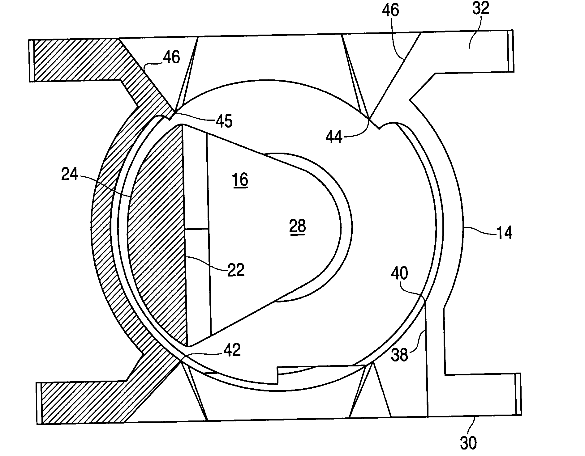
[0032] The present invention in some embodiments provides an improved plug valve and flow control method with cylindrical seating that can at least to some degree enhance fluid flow and / or ameliorate the effect of suspended solids use. A preferred embodiment will now be described with reference to the drawing figures, in which like reference numerals refer to like parts throughout.

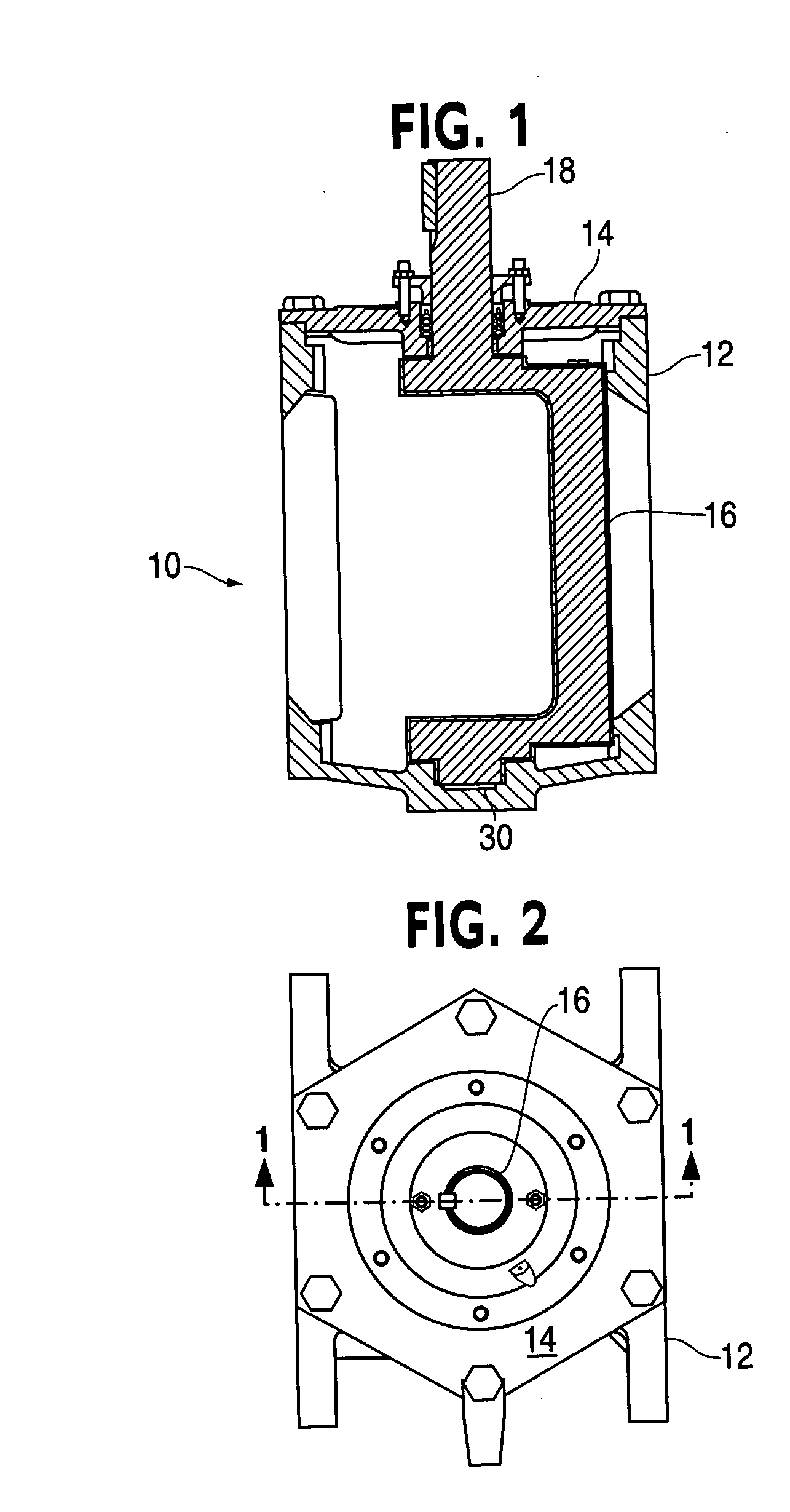
[0033]FIG. 1 illustrates a plug valve 10 according to a preferred embodiment of the invention, including a body 12, a bonnet 14, and a valve plug 16. The valve plug 16 is rotatably mounted within the chamber formed by the housing 12 and the bonnet 14 and is moveable between open and closed positions as will be described in more detail below. FIG. 2 is a top view of the arrangement shown in FIG. 1 and further illustrates the housing 12, bonnet 14 and a shaft portion of the valve plug 16.

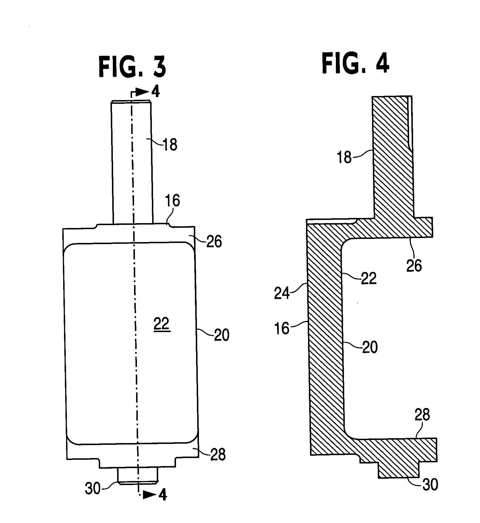
[0034] Turning now to FIGS. 3 and 4 in particular, the valve plug 16 is illustrated to have the shaft 18, a plug region ...


PUM


Abstract

An apparatus is provided that in some embodiments provide an improved plug valve having a plug with a curved cylindrical sealing surface and a substantially flat second surface. An inlet region of the housing has a constant cross-sectional flow area.

Description

FIELD OF THE INVENTION [0001] The present invention relates generally to the field of eccentric plug valves which may be used to control the flow of fluid in pipe systems. BACKGROUND OF THE INVENTION [0002] Eccentric plug valves have been available to industry for some time, and typically include a main body having an inlet port and outlet port and a plug mounted for rotation about a shaft, so that a plug face is eccentrically rotated to either close off or open flow through a valve seat area. Such valves are used, for example, in wastewater, mining, fresh water, and many other industrial and HVAC services. [0003] The plug valves typically have a long service life and are known for their reliability. Many of the valves are sold for use in sludge and slurry services such as wastewater, ash, mining tailings, and other similar applications. Eccentric plug valves generally include two types: wherein the rotatable plug and mating seat is either cylindrical or spherical. [0004] Cylindrica...

Claims


Application Information

Patent Timeline
IPC IPC(8): F16K5/00
CPCF16K5/0407
Inventor LIBKE, ALBERT W.JANAGAN, PARANTHAMAN
Owner DEZURIK
Why Eureka
Try Eureka