
Adjustable annuloplasty device with alternating peaks and troughs

a technology of annuloplasty and trough, which is applied in the field of valve repair, can solve the problems of regurgitation of blood from the ventricle through the valve into the atrium, and achieve the effect of facilitating deflection or pivoting of tissue anchors

Active Publication Date: 2018-01-11
VALTECH CARDIO LTD
View PDF4 Cites 76 Cited by
  • Summary
  • Abstract
  • Description
  • Claims
  • Application Information

AI Technical Summary

Benefits of technology

The patent describes a way to attach a ring to a device in a way that allows for easy installation. The technical effect of this invention is that it simplifies the process of attaching a ring to a device, making it more accessible to users.

Problems solved by technology

Dilation of the annulus of atrioventricular heart valves, such as the mitral valve, prevents the valve leaflets from coating effectively when the valve is closed, thereby resulting in regurgitation of blood from the ventricle through the valve into the atrium.

Method used


Image

  • Adjustable annuloplasty device with alternating peaks and troughs
  • Adjustable annuloplasty device with alternating peaks and troughs
  • Adjustable annuloplasty device with alternating peaks and troughs

Examples


Embodiment Construction

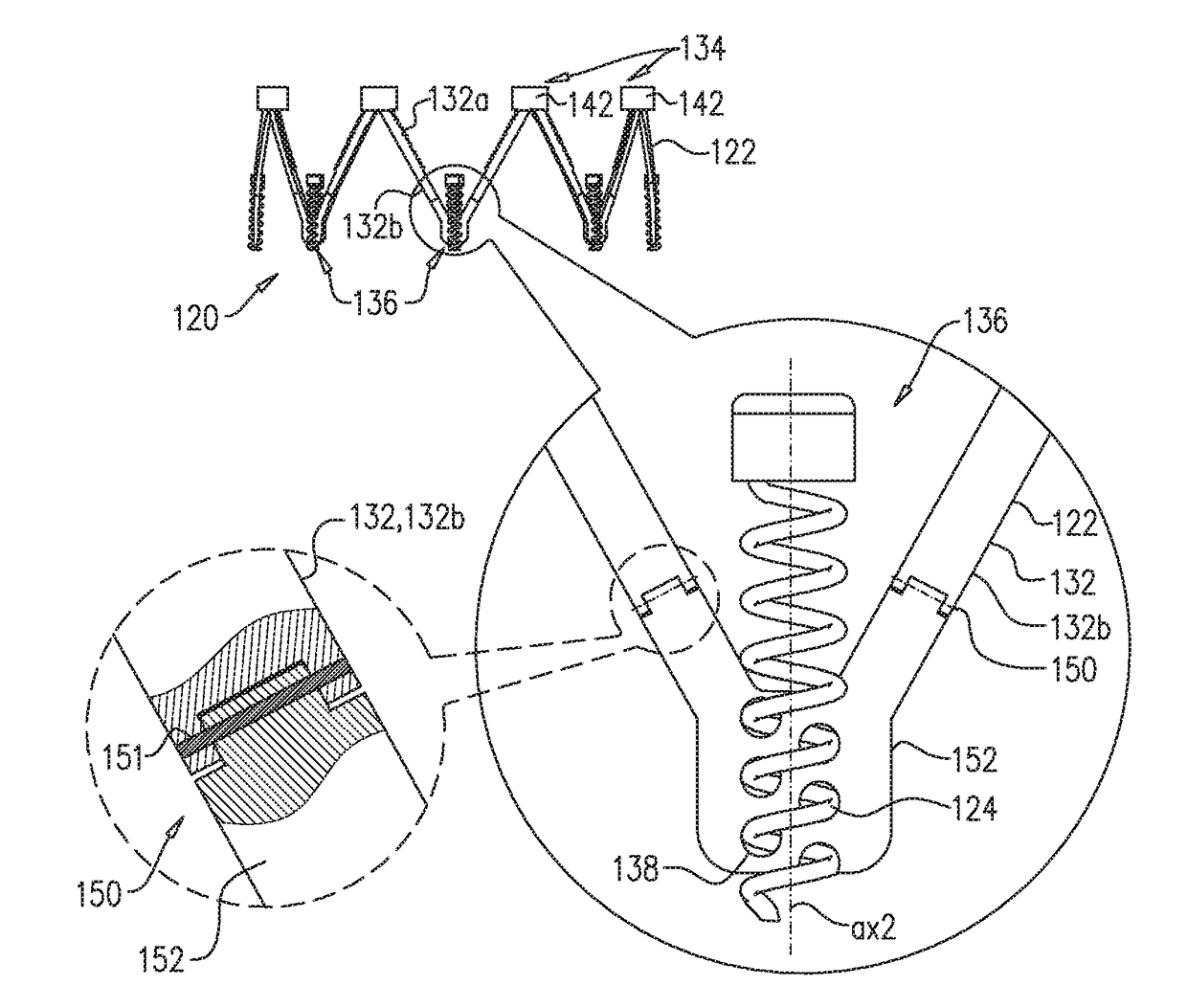
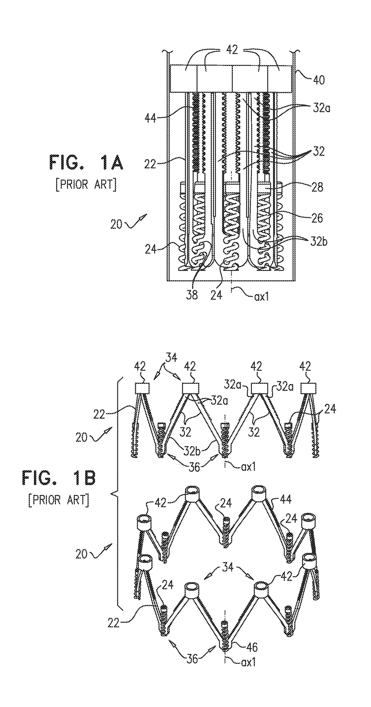
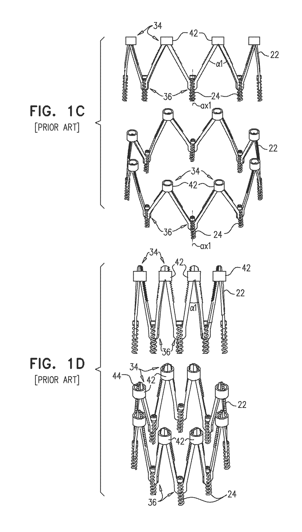
[0057]Reference is made to FIGS. 1A-D, which are schematic illustrations of a prior art implant 20 shown in U.S. Pat. No. 9,180,005, for use at a valve (e.g., a mitral valve) of a heart of a subject, in accordance with some applications of the invention. Implant 20 comprises a ring 22 and a plurality of (e.g., 8) anchors 24. Ring comprises a plurality of struts 32 arranged in a pattern of alternating peaks 34 and troughs 36 (e.g., in a zig-zag pattern). Each strut 32 has a first end-portion 32a and a second end-portion 32b. Each peak 34 is defined by convergence of adjacent first end-portions 32a (i.e., of first end-portions 32a of adjacent struts 32), and each trough 36 is defined by convergence of adjacent second end-portions 32b (i.e., of second end-portions 32b of adjacent struts 32).

[0058]Each anchor 24 has a longitudinal axis ax1 along which it is configured to be driven into tissue of the annulus of the valve of the heart of the subject, and is coupled to ring 22 at a respect...


PUM


Abstract

Apparatus is provided, comprising a ring, comprising a plurality of struts arranged in a pattern of alternating peaks and troughs, each strut having a first end-portion and a second end-portion, each peak defined by convergence of adjacent first end-portions disposed at an angle with respect to each other, and each trough defined by convergence of adjacent second end-portions. The apparatus also comprises a plurality of anchors. Each anchor has a longitudinal axis, is configured to be driven along the longitudinal axis into tissue of the heart, and is coupled to the ring at a respective trough in a manner that facilitates (i) movement of the anchor along the longitudinal axis with respect to the trough, and (ii) deflection of the longitudinal axis with respect to the trough.

Description

CROSS-REFERENCE TO RELATED APPLICATIONS[0001]The present application claims priority from UK Patent Application GB1611910.9, filed Jul. 8, 2016, and entitled “ADJUSTABLE ANNULOPLASTY DEVICE WITH ALTERNATING PEAKS AND TROUGHS,” which is incorporated herein by reference.FIELD OF THE INVENTION[0002]The present invention relates in general to valve repair. More specifically, the present invention relates to repair of a cardiac valve of a patient using an adjustable implant.BACKGROUND[0003]Dilation of the annulus of atrioventricular heart valves, such as the mitral valve, prevents the valve leaflets from coating effectively when the valve is closed, thereby resulting in regurgitation of blood from the ventricle through the valve into the atrium. Annuloplasty is a known surgical technique for treatment of a dilated valve annulus. U.S. Pat. No. 9,180,005 to Lashinski et al., which is incorporated herein by reference, relates to an adjustable mitral valve ring for minimally-invasive deliver...

Claims


Application Information

Patent Timeline
Patent Type & Authority Applications(United States)
IPC IPC(8): A61F2/24
CPCA61F2/2445A61F2220/0091A61F2220/0016A61F2250/0008A61F2250/0012A61F2250/0006A61F2250/0029
Inventor KUTZIK, MEIRBRAUON, HAIMLEVIN, MICHAELFOGEL, ALONHARITON, ILIAREICH, TAL
Owner VALTECH CARDIO LTD
Learn More