Optical module

a technology of optical modules and optical fibers, applied in the field of optical modules, can solve the problems of increasing the cost of assembling the optical modules, affecting the performance of the optical modules, so as to achieve the effect of low cost and less likely to be damaged

Active Publication Date: 2018-01-11
LUMENTUM JAPAN INC
View PDF1 Cites 11 Cited by
  • Summary
  • Abstract
  • Description
  • Claims
  • Application Information

AI Technical Summary

Benefits of technology

[0010]Therefore, the invention aims at providing an optical module which is less likely to be damaged, and can be assembled at low cost.

Problems solved by technology

In this case, the optical fiber is required to be bent at about a 90 degree angle, which would impose a load on the optical fiber, thereby damaging the optical fiber.
In this case, the optical component is required to be aligned to the substrate precisely, which may increase cost of assembling the optical module.
However, such arrangement may make it difficult to connect the electrical signal port to the substrate because the electrical signal port is arranged parallel to the base plane of the optical module so as to obey a standard of the optical module.

Method used


Image

  • Optical module
  • Optical module
  • Optical module

Examples


Embodiment Construction

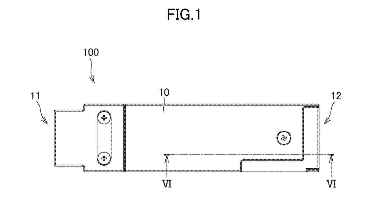
[0028]FIG. 1 shows a plan view of an optical module 100 according to an embodiment of the invention. The optical module 100 comprises a housing 10 having an electrical signal port 12 for an electrical signal and an optical signal port 11 for an optical signal. The housing 10 is made of metal, and blocks electromagnetic radiation generated inside the housing 10.

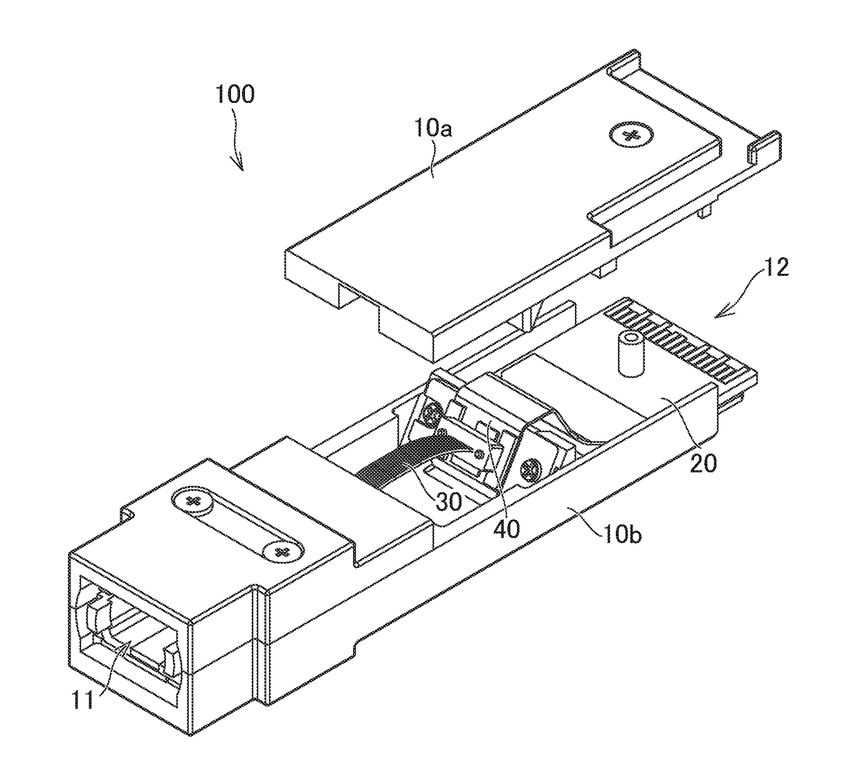
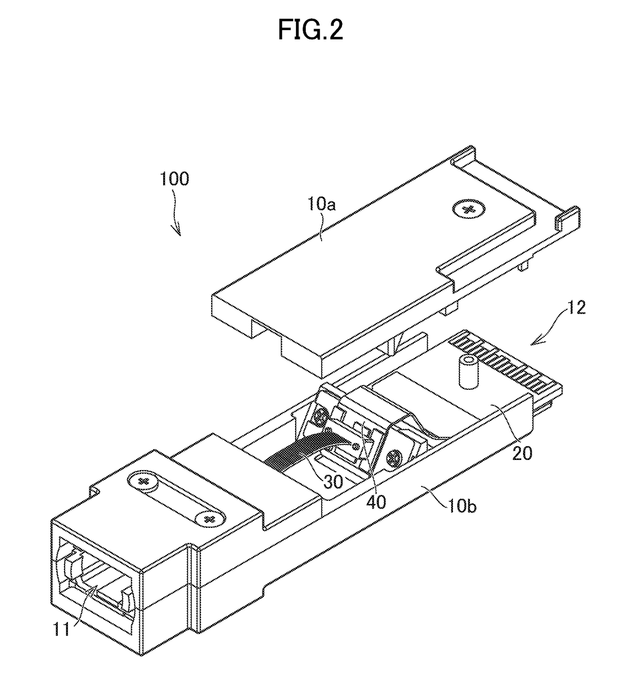
[0029]FIG. 2 shows an exploded perspective view of the optical module 100 according to an embodiment of the invention. In FIG. 2, the housing 10 is shown with its exploded state. The optical module 100 comprises the housing 10, a first substrate 20, an optical fiber 30 and a second substrate 40. The housing 10 consists of an upper part 10a and a lower part 10b, and includes the first substrate 20 such that the first substrate 20 is held between the upper part 10a and the lower part 10b. The upper part 10a and the lower part 10b are fixed with each other by screws.

[0030]The first substrate 20 is arranged in the housing 10 so as...


PUM


Abstract

The invention provides an optical module which is less likely to be damaged, and can be assembled at low cost. The optical module comprises a housing having an electrical signal port for inputting and / or outputting an electrical signal and an optical signal port for inputting and / or outputting an optical signal, a first substrate arranged in the housing so as to connect to the electrical signal port, an optical fiber arranged in the housing so as to connect to the optical signal port, and a second substrate provided with an optical device which connects to the optical fiber to input the optical signal from the optical fiber and output the optical signal to the optical fiber, and arranged in the housing so as to electrically connect to the first substrate, and to be inclined with respect to a base plane of the housing.

Description

CROSS-REFERENCE TO RELATED APPLICATION[0001]The present application claims priority from Japanese application JP 2016-136710, filed on Jul. 11, 2016, the content of which is hereby incorporated by reference into this application.BACKGROUND OF THE INVENTION[0002]1. Field of the Invention[0003]The invention relates to an optical module.[0004]2. Description of the Related Art[0005]An optical module is known that is formed by integrating a light emitting module which converts an electrical signal to an optical signal with a light receiving module which converts an optical signal to an electrical signal. The optical module comprises an electrical signal port for the electrical signal and an optical signal port for the optical signal.[0006]JP 2008-257094A discloses an optical transmission module comprising a housing and an inclination portion on the inner surface of the housing on which a circuit board is arranged.SUMMARY OF THE INVENTION[0007]Either one of the optical and electrical sign...

Claims


Application Information

Patent Timeline
Patent Type & Authority Applications(United States)
IPC IPC(8): G02B6/42
CPCG02B6/4256G02B6/428G02B6/4279G02B6/4246G02B6/421G02B6/4245G02B6/4269G02B6/4281G02B6/4284G02B6/4292G02B6/4214
Inventor OMORI, KOICHIIRIE, HIROKIAOKI, TETSUYA
Owner LUMENTUM JAPAN INC
Why Eureka
Try Eureka