Optical lattice clock at operational magic frequency and method for operating the same

a technology of optical lattice clock and magic frequency, which is applied in the direction of automatic control of pulses, electrical apparatus, and apparatus using atomic clocks. it is difficult to determine the optimal lattice frequency to confine atoms just by optimizing, and the lattice-lattice intensity i in the optical lattice clock is highly sensitive. it reduces systematic uncertainty, minimizes uncertainty, and is convenient to us

Active Publication Date: 2018-01-11
RIKEN
View PDF0 Cites 1 Cited by
  • Summary
  • Abstract
  • Description
  • Claims
  • Application Information

AI Technical Summary

Benefits of technology

[0021]In accordance with an aspect of the present disclosure, a highly practical optical lattice clock and method for operating the same is provided. In one example, a design strategy is provided with respect to highly practical optical lattice clocks that allow us to operate them with a well-defined operation over an extended range of lattice-laser intensity while assuming necessary corrections on the clock frequency values. Another example with another design strategy is provided also for a highly practical optical lattice clock that allows us to operate the clock with a well-defined operation over an extended range of lattice-laser intensity without requiring correction to the clock frequency values with minimized uncertainty. Consequently, optical lattice clocks using several types of atom can be operated with reduced systematic uncertainty of less than 10−17, as an example.

Problems solved by technology

However, when uncertainty of the optical lattice clock is to be reduced to less than 1×10⁻¹⁵ or 1×10⁻¹⁶ level, it is difficult to determine the optimal lattice frequency to confine atoms just by optimizing in a cut-and-try manner.
As will be explained later, the inventor have found that the shift of the clock transition due to the light-shift perturbation depends on the intensity of the lattice laser in a complicated nonlinear manner, which disables linear-extrapolation-to-zero approach and makes the corrections highly delicate issue (Non Patent Literatures 2 and 3).
Therefore, the lattice-laser intensity I in the optical lattice clocks may vary over a relatively wide range in actual operation conditions and cannot be controlled to an optimal value even when it has been carefully determined.

Method used


Image

  • Optical lattice clock at operational magic frequency and method for operating the same
  • Optical lattice clock at operational magic frequency and method for operating the same
  • Optical lattice clock at operational magic frequency and method for operating the same

Examples


Embodiment Construction

[0029]An embodiment of an optical lattice clock of the present disclosure is described below by referring to the drawings. In the following description, common parts or elements are indicated by common reference numerals over the entire drawings unless otherwise noted. In addition, each element in the drawings is not necessarily drawn to scale.

1. Structure of Optical Lattice Clock

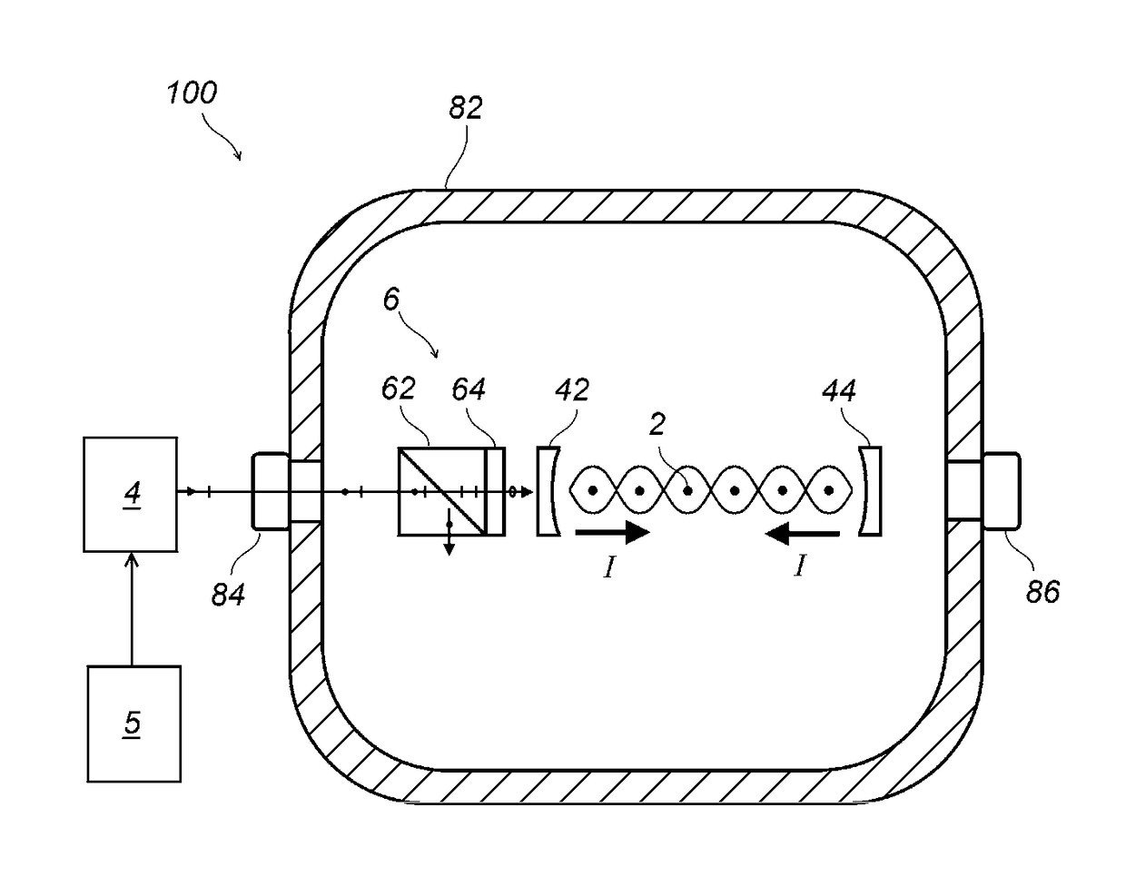
[0030]FIG. 1 is a schematic diagram indicating an example structure of the optical lattice clock of the present embodiment. An optical lattice clock 100 measures transition frequency between electronic states of atoms 2. The atoms 2 are selected from a group of atoms or ions having clock transitions between long-lived states, and, in particular, from a group consisting of ytterbium (Yb), mercury (Hg), strontium (Sr), cadmium (Cd), zinc (Zn), magnesium (Mg), and calcium (Ca). Among the transitions of the electronic states of the atoms 2, a transition whose transition frequency is measured using laser spectro...


PUM


Abstract

An embodiment of an optical lattice clock comprising atoms and a laser light source at an operational magic frequency is provided. The atoms are capable of making a clock transition between two levels of electronic states, and the laser light source generates at least a pair of counterpropagating laser beams, each of which having a lattice-laser intensity I. The pair of counterpropagating laser beams forms an optical lattice potential for trapping the atoms at around antinodes of a standing wave created by it. The operational magic frequency is one of the frequencies that have an effect of making lattice-induced clock shift of the clock transition insensitive to variation ΔI of the lattice-laser intensity I, the lattice-induced clock shift being a shift in a frequency for the clock transition of the atoms caused by the variation ΔI of the lattice-laser intensity I.

Description

TECHNICAL FIELD[0001]The present disclosure relates to an optical lattice clock. More specifically, the present disclosure relates to an optical lattice clock for performing time measurement with reduced uncertainty by using an operational magic frequency and a method for operating the same.BACKGROUND ART[0002]Atomic clocks have been used for a time reference these days. The atomic clocks are also used in application fields that require high precision in time measurement. They use electromagnetic waves in a microwave range for frequency reference, which waves are produced through transitions between electronic levels in atoms such as Cs (caesium) and Rb (rubidium). For further precise measurement of time, devices called optical clocks have been developed.[0003]The last few years have witnessed significant advances in optical clocks to reach uncertainties of 10−18 level in ion-based clocks and optical lattice clocks. Hitherto unexplored accuracy of optical clocks opens up new possibi...

Claims


Application Information

Patent Timeline
Patent Type & Authority Applications(United States)
IPC IPC(8): G04F5/14H03L7/26
CPCG04F5/14H03L7/26
Inventor KATORI, HIDETOSHI
Owner RIKEN
Why Eureka
Try Eureka