
Ladder filter and duplexer

a duplexer and ladder filter technology, applied in the direction of impedence networks, electrical equipment, etc., can solve the problems of ladder filter insertion loss, insertion loss is large, impedance matching is degraded, etc., to reduce insertion loss, improve out-of-band attenuation, outstanding impedance matching

Active Publication Date: 2018-01-11
MURATA MFG CO LTD
View PDF7 Cites 53 Cited by
  • Summary
  • Abstract
  • Description
  • Claims
  • Application Information

AI Technical Summary

Benefits of technology

The present invention provides ladder filters and duplexers that can improve out-of-band attenuation, achieve outstanding impedance matching, and reduce the insertion loss. Specifically, the ladder filters have a narrowed capacitive frequency range, resulting in improved impedance matching. The duplexer includes the ladder filter, further reducing the insertion loss. The filters and duplexer are made using surface acoustic wave resonators. These technical effects make the ladder filters and duplexer ideal for use in various electronic devices.

Problems solved by technology

Accordingly, impedance matching is degraded and insertion loss is increased.
Accordingly, the ladder filter has large insertion loss even when the electrostatic capacitance of the second parallel arm resonator is decreased.

Method used


Image

  • Ladder filter and duplexer
  • Ladder filter and duplexer
  • Ladder filter and duplexer

Examples


Embodiment Construction

[0037]The present invention will be described with reference to specific preferred embodiments of the present invention and the attached drawings.

[0038]The preferred embodiments described in the description are only examples and components in different preferred embodiments may be partially replaced or combined.

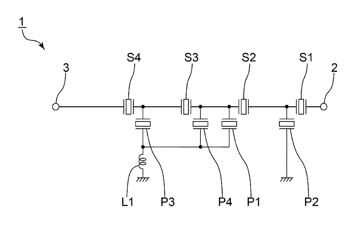
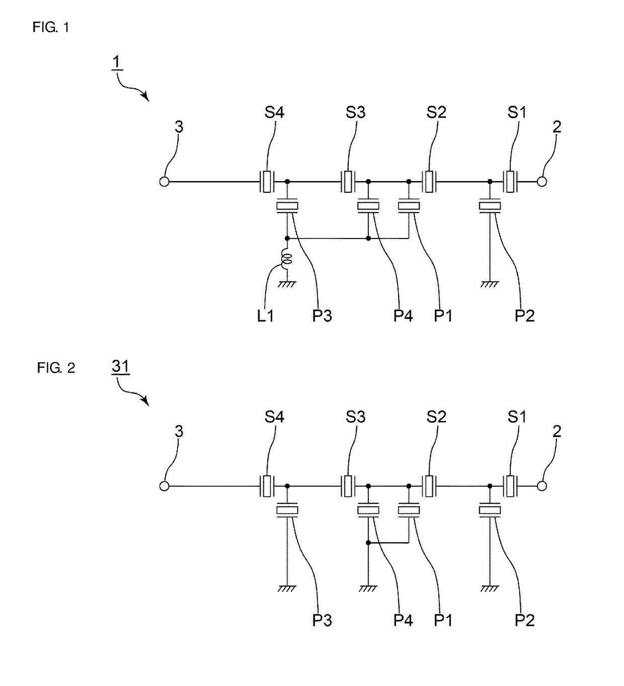
[0039]FIG. 1 is a circuit diagram of a ladder filter according to a first preferred embodiment of the present invention.

[0040]A ladder filter 1 includes a serial arm connected between an input terminal 2, which is an input end, and an output terminal 3, which is an output end, and multiple serial arm resonators S1 to S4 provided on the serial arm. In addition, the ladder filter 1 includes parallel arms connected between the serial arm and a ground potential and a first parallel arm resonator P1, second parallel arm resonators P2 and P3, and a third parallel arm resonator P4 provided on the parallel arms. More specifically, the first parallel arm resonator P1 and the third par...


PUM


Abstract

A ladder filter in which the pass band is defined by serial arm resonators and first and second parallel arm resonators includes the serial arm resonators, the first and second parallel arm resonators, and a third parallel arm resonator. The third parallel arm resonator is connected in parallel to the first parallel arm resonator, the electrostatic capacitance of the third parallel arm resonator is smaller than that of the first parallel arm resonator, and the anti-resonant frequency of the third parallel arm resonator is positioned outside the pass band of the ladder filter. The anti-resonant frequency of the first parallel arm resonator is positioned at the high frequency side of the anti-resonant frequencies of the second parallel arm resonators.

Description

CROSS REFERENCE TO RELATED APPLICATIONS[0001]This application claims the benefit of priority to Japanese Patent Application No. 2015-092801 filed on Apr. 30, 2015 and is a Continuation Application of PCT Application No. PCT / JP2016 / 057414 filed on Mar. 9, 2016. The entire contents of each application are hereby incorporated herein by reference.BACKGROUND OF THE INVENTION1. Field of the Invention[0002]The present invention relates to a ladder filter and a duplexer.2. Description of the Related Art[0003]Ladder filters have been widely used in cellular phones and other suitable devices.[0004]International Publication No. 2013 / 080461 discloses an example of a ladder filter. This ladder filter includes multiple serial arm resonators and multiple first parallel arm resonators, which compose a pass band. The ladder filter also includes a second parallel arm resonator having a resonant frequency that is positioned at the high frequency side of the anti-resonant frequency of the multiple seri...

Claims


Application Information

Patent Timeline
IPC IPC(8): H03H9/64
CPCH03H9/6483H03H9/725H03H9/6423
Inventor TAKATA, TOSHIAKI
Owner MURATA MFG CO LTD
Learn More